Electrical Drawings - Showing Wiring Terminals

As this is drawn, it shows that yes, there are two wires at the connection point 13 of contact -FC4 with no terminal in between. This style of drawing may take some getting used to but actually shows how things should be wired quite clearly.

Please don’t misunderstand me, I’m all in favor of clearly drawn and accurate prints. But a symbol is just a symbol no matter if it is a 45 degree angle (as described in one of the earlier posts) or a dot that means wires are connected.

It’s all in what you get used to using.
 
Of course. But an angle-style connection symbol does have some meaning in advanced controls design systems like AutoCAD Electric or EPLAN (which is, I guess, is what was used to draw this example). By analyzing the connection symbols as they are drawn, the software can generate an accurate connections list for the wiring shop which tells exactly how the thing should be wired: take 22 ga brown wire and run it from terminal -X2.1 on the left to point 13 of switch -FC4, then run another brown wire from point 13 of switch -FC4 to whatever is on the the right of it... and so on.

With a dot as a connection symbol, a lot of this has to be figured out by a wiring guy on his own. Which is fine if the wiring guy is you or your buddy in the shop next door. But does not always work smoothly if a panel was sent for wiring to an outside contractor.
 
It is called "wiring-correct schematics" or something to that effect - I dont have the english name for it.
It does take some effort by the person doing the schematics. He has to consider the best way to make the wiring when he do the schematics. Of course the panel builder can decide to make it different, if only he report it back to the schematics guy who then update the diagrams accordingly.

We use this method in all or diagrams now. We only use the dot when there is a bus-bar and connections are tapped off the busbar in the way that the dot symbol indicates.
 
I had to change two Parker drives on a German-made Huber dewatering system today. Both were making a lovely bang when powered up. Detailed drawings, but not a single wire labeled within the panel.

Had to add insulation tape labels to each wire during the change. Real pain in the *** for a Friday afternoon breakdown, too much thinking involved!

Yeah, I feel your pain. I got sent down the Athens, AL to fix a Wagner paint booth a few years ago. No wire labels on this beast either...
 
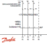
This is how we draw ours. Terminals are shown as circles with a diagonal, connection points in devices as circles with a leg.

Capture.PNG
 

Similar Topics

Hi everyone, I'm in search of software for electrical drawings, preferably free but also interested in paid options. Any recommendations or...
Replies
33
Views
1,537
I've had a bit of a curly one come up today and I'm not sure how best to approach it. Interested to hear if anyone else has had this experience...
Replies
29
Views
8,785
Is there a standard list of Letters (prefixes) for components on an electrical drawing Eg. CB = Circuit Breaker U = Power supply F = Fuse
Replies
8
Views
2,506
I use the non-electrical version of autocad. I am looking for a way to modify all of the line numbers at once. It would be great if I could make...
Replies
15
Views
6,641
Hi! This maybe a non-PLC-programming-question, but still related to PLC. What is the typical electrical CAD drawings order in a set for a single...
Replies
10
Views
4,555
Back
Top Bottom