Question in programming Siemens PLC..

stevenPLC

Member
Join Date
Sep 2004
Posts
27
Hi all my expert friends...I'm still new with Siemens PLC and I am using the Siemens PLC model S7-300 (CPU315-2 DP). I am facing some programming issues as follows:

1) The PID configuration - The PID action is not correct. Its action is at only one way even when the PV > SP or PV < SP. What's the most proper method to configure the PID? I'm using the FB41 CONT_C function block.

2) I need to do some program to detect actual time of 1 sec. But the Sec Timer used in program unable to detect accurately 1 sec (compare to actual time of 1 second). Any configuration or method to avoid this?

PLZ...can any of our experts help me oUT ASAP? PLZZ..
Thank you.. <"o">..
 
Hi,
It's hard to tell what's wrong with your PID config without possibility to have a look at it.
Regarding your second question: what do you mean by "detect actual time of 1 sec" ? Do you wanna measure duration of some signal or just generate precise pulse ?
What kind of timer do you use and how you parametrized it ?
In case of S7 timer accuracy depends on selected time base and program scan time. IEC timers are affected only by scan time as their resolution is 10 ms in S7-300.
 
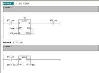
My ladder diagram..

Yes, actually I would like to generate a 1 sec pulse, which will be used to capture some data reading every 1 sec.

If I'm not wrong (Plz correct me if I'm wrong cause I'm still new to Siemens PLC), I'm using the S5 Timer.

My ladder is as shown in the attached jpg file. Plzz have a sneak and comment. How can I configure or use what better type of timer or do anything to achieve my pupose??
Thankz..

s7_prob.jpg
 
Accuracy can be improved a little bit by coding the network with timer in STL. The reason is that timer is reset in next scan.
That is LAD timer call translated into STL
A M 0.1
L S5T#1S
SP T 0
A M 0.0
R T 0 <- 2) so timer will be reset in next cycle
NOP 0
NOP 0
A T 0
= M 0.0 <- 1) here status of timer is read
You could change this to something like this:
A M 0.1
L S5T#1S
SP T 0
A T 0
= M 0.0 <- 1) here status of timer is read
A M 0.0
R T 0 <- 2) so timer is reset in this cycle

SP timer is here used as example only.

If it won't help you much. You can try executing your logic in timed interrupt.
You must know one more thing. When you read from AI module what you read is not present value of input signal. This is value obtained during previous conversion cycle. In some AI module this conversion cycle is as long as 200 ms.
 
If it's only 1 move command, you can put that in OB 35 and set the interrupt time to 1000ms

OB35 is in your properties tab of the CPU..

It's the most precise way to do it !
 
Or just use the built-in clock byte. You nominate whichever M-byte you want (say MB0) and then all 8 bits are automatically toggled on and off as equal mark/space square waves at different fixed frequencies from 10Hz at M0.0 to 0.5Hz at M0.7. For a regular 1-second pulse just check for the rising edge of M0.3 which is on a 2Hz frequency (1/2-sec on, 1/2-sec off)

Ken
 
I like NAK's solution better. Just move the MOVE statement to OB35 and set the interrupt time to 1000, instead of the default time of 100ms. Delete every thing about the timer. It will move your data 1 time every 1 sec and is the most reliable. The System clock bits are not as accurate and are ON and OFF at 50% intravals.
The PID is another matter. I found it useful to use the Siemens PID demo. Show us a picture of what you have connected to FB41. Make sure you download the Instance DB that is associated with FB41. It don't download into the PLC, automagicly (new word).
 
Steve,

If you still want to use a regular timer to generate the pulse (perhaps you have a bunch of other things you want to do once each second that shouldn't be in an interrupt block), then you can do it much simpler than as it's coded above.

In STL, it looks like this (I'm using M10.0 as the pulse bit, but use anything you want):

AN M10.0
L S5T#1S
SD T1
A T1
= M10.0

Now, M10.0 will pulse as a one-shot every second, and you can use it throught your program. Just a suggestion.
 
What I usally do is to use the clock bits (as mentioned before) on a 10Hz frequency and the feeding this into an STL counter (hardcoded not the built-in Counters (C#)).
Then I just increment my counter every 100Ms, the only thing (as far as I know) thats affecting the precision is the scan time of the plc, but on a 100Ms base the timer should be off by maximum 50Ms.
Using this system you can also have longer and shorter times, just change whatever you'r comparing to.

I can post the STL code for this if it's interesting.

Regards
Borte
 

Similar Topics

I have the following code in My S7-300 function block: AN #Dig_IN_GLYCOL_LVL_OK S #ALM_LO_GLYCOL_LVL AN #FLAG_CHILLER_ENABLE AN...
Replies
7
Views
2,221
Could anyone tell me how to reset a counter in a particular time in a day , say 8 a.m. and 8 p.m. in Simatic S7 system. If anyone provide me an...
Replies
3
Views
2,185
Hi, I'm wondering how to program a function that has an integer(or word) input but return the value contains in the address of the input. for...
Replies
8
Views
4,022
I'm new to the Siemens plc and Step7 software. I have a S7-200 and I like to combine a bunch of alarm bits (%m10.0-%m10.7 & %m11.0-%m11.7) into...
Replies
1
Views
3,011
S
Hi all my expert friends...I'm still new with Siemens PLC and I am using the Siemens PLC model S7-300 (CPU315-2 DP). I am facing some programming...
Replies
0
Views
9,135
stevenPLC
S
Back
Top Bottom