Asefakaratas
Member

Hi everyone first of all.
This is first question in the forum. I am using HSC application. I'm reading A and B pulse count.
1 round of the motor : 36000 pulse
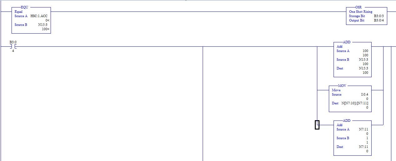
And, I want to read a sample from the sensor in every 100 pulses. That means 360 samples in 36000 pulse. But I have a problem. When I use a comparator, I can't keep up with the speed of the Accumulator.
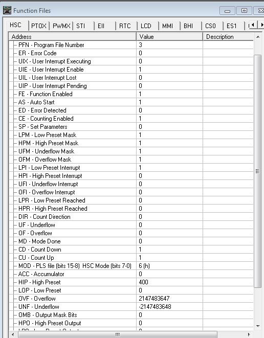
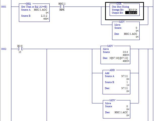
Example; Counter is 72000. So 720 sample. When HSC start I need 720 rising edge. But not fast. What can I ? Does interrupt work ? If yes How ?
This is first question in the forum. I am using HSC application. I'm reading A and B pulse count.
1 round of the motor : 36000 pulse
And, I want to read a sample from the sensor in every 100 pulses. That means 360 samples in 36000 pulse. But I have a problem. When I use a comparator, I can't keep up with the speed of the Accumulator.
Example; Counter is 72000. So 720 sample. When HSC start I need 720 rising edge. But not fast. What can I ? Does interrupt work ? If yes How ?