ControlLogix
Member
Hi guys,
I have another question for you...not scantimes this time but vision systems.....Arrrggghhh!
Let me explain...
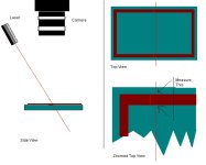
I have an Epson robot that places an rectangular pattern on a plastic body prior to silicon base components being placed upon it. If one was to draw a box around the pattern it would measure approximately 25mm wide and 40mm long. The adhesive is a continuous bead whose thickness on the black plastic body should be 0.4mm all around the pattern.
A vision system measures the bead pattern 10 seconds after it has been dispensed onto the plastic body. The vision system consists of a light ring approximately 20mm above the body with an inner and outer LED ring so the light can be varied across the plastic body. Attached to the bottom of the ring is a polariser. Approximately 100mm above this is a camera with a polariser as well(Melles Griot camera).
There is no problem calibrating the vision system so that the vision system can match images to real world co-ordinates...simple and extremely robust. However, when it comes to measuring the bead thickness, the whole system becomes very flakey. By varying the power of the two LED rings one can vary the thickness of the bead (as determined by the vision system). Therefore, a bead that might actually be 0.5mm wide can be made to read as 0.3mm or 0.6mm on the vision system depending on how you vary the light.
The adhesive is white, the pen body is black...how do I set my system up so that I know that when I put a pen under the camera I know that the results that come back are true....I can't measure the bead and then place it under the camera since it settles over time and a few seconds can make a huge difference!
Any further details just let me know....I don't know have I explained myself well enough!


