DC Power Distribution

Join Date
Apr 2002
Location
Just a bit northeast of nowhere
Posts
1,117
I have a feeling this one will be contentious :)

First, let's define what I mean by "DC Power" : 24-volt supply and common lines to sensors and solenoids. They don't get switched at any point by anything, and are always at the same voltage level throughout their run. They may be connected directly to the main panel, or via a sub-panel.

That said, I've seen many, many methods of documenting the run of DC power through a machine, from simply ignoring it to a separate number for each branch to each sub-panel. In fact, I can't recall seeing the same exact method twice!

So, let's discuss a few basics :

1. How important is it to document the precise run of the DC supply through the system? Given it's nature and purpose, as long as the wires are marked "+DC" and "0DC", does the conductor on the schematic really make a difference?

2. If it is critical, what's the best approach to documenting it? Should the run be lumped with the IO it supplies, or is a branching scheme (like mine) acceptable? Vertical ladder rails? What about those weird (to me, heh heh) "buss-bar" symbols?

Examples to follow

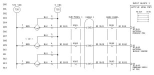
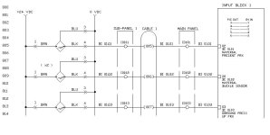
The "I know it's there" approach :

There is a variation of this one - the "Always One Wire Number" approach.
dc1.jpg
 
Last edited:
Tim
You are bored .

All your method OK except in the first one, its look like you feed your 24V by connector, if you do, Please write the numbers of the contacts on your DWG.

Arik
 
I wish...

Hi Arik!

No, not bored, just mildly obsessed.

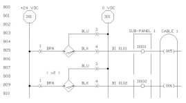
A number of people have taken exception to the method I was using to document my DC power runs (mine is option 3), so I wanted to see if there is a more standard approach.

Given the variety I've seen, I rather doubt it, but heck, it was worth a shot :)

Truth is, I'm not bored, just sick to death of schematics ::sigh:: Happily, I can get my hands on some actual equipment tomorrow and Sunday, which will go a long ways towards relieving my paranoia about my schematics techniques.

Thanks for the reply! (And I really do need some benchmarks to compare myself to)

TM
 
Last edited:
"times 2". In that circuit, two identical proxes are connected in parallel, so either can trigger the input. This was stated in the input description, whcih got cut off in the picture.

Thanks!

Edit : Or was supposed to be, anyhow. Thanks for pointing that out, I'll fix it.

TM
 
Tim,

I generally label my "power" wires according to the fuse or circuit breaker that protects them. For instance, if a wire is protected by fuse "F1" then I might label the wire "FP1" for fused power 1. If another wire is protected by fuse "F23" then I will label the wire "FP23", and so on. I have found that it makes my life a little easier when troubleshooting a machine.

I always use the same number for all of the common wires.

Kevin
 
I'm not overly concerned about how you specify references to other pages, but I think you should show how the DC gets distributed throughout the machine. You could even dedicate a separate page to show the distribution. I'm sure you've seen 'ground distribution' drawings.

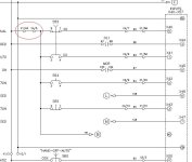
Let's say the +24VDC is shorted somewhere. In order to locate the short, you need to isolate where the short lies. Use this snippet from page 2 of my previously posted example.
[attachment]
Notice the terminal numbers I circled in red. This circuit is, by your "DC Power" definition, +24VDC (my wire #18). By following my schematic, I know if I disconnect the wire between terminal X1/63 and X4/5 (by disconnecting the wire at either terminal), I can ISOLATE S52, S54, S55, and reference "B" (which happens to go to the Operator Panel on page 1). If the short remains, I can assume that it has nothing to do with these items. If the short goes away, I can concentrate my search on ONLY these items... (y)

If you just show that stuff gets connected to power 'somewhere', it makes it difficult to troubleshoot... banghead

beerchug

-Eric

By the way, to clarify, "X4/5" means terminal strip "X4", terminal number "5". This would make sense if you saw the panel. The terminal strip is labeled "X4" at the top.

circuit.jpg
 
Wire and fuse labeling should be somehow related:

Fuse for common 24 VDC internal in control panel: -QD01
Wire labeling for above voltage: -LD01
Distributing terminals for above voltage: -XD01
If there is a short circuit in the internal 24 VDC (extremely rare), then the terminal strip allows you to disconnect the wires and reconnect them one-by-one.

The same principle applies to 24VDC that are used in the plant or on the machine. Only as the probability that a short might occur outside of the panel, the 24 VDC is broken down into several groups - each with its own fuse.
Also, for the connection to the outside of the panel I use terminals with a builtin isolator switch (only for the terminals that supply 24 VDC). This greatly assists in locating the "bad" connection.
 
I, too, would draw the second prox, especially in an unusual connection like that.

I have seen your option #3 the most in the field. Used as a standard by companies that have been around decades.

I use a variation of #1 with a slightly different symbol, as like ArikBY said, it looks like a connector.
 
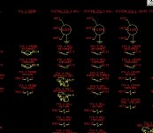
We also add some pages at the end of the schematic with all the field devices grouped together per machine station. When the machine is wired, they use these sheets almost exclusively.

layout.jpg
 

Similar Topics

In our PLC, we've got a 24VDC (5 amp) power supply - it's a PULS cp5, which connects to a DIN rail. I need it to supply power to 8 x Druck...
Replies
2
Views
1,118
Does anyone know of a clever way to distribute 480 vac, three phase voltage for applications over 100 amps? I have a project where the customer...
Replies
18
Views
5,490
We are working on a project that includes the requirement for us to provide a 400A 480vac distribution panel with breakers to supply the 3-phase...
Replies
8
Views
4,462
Hello Guys, I have a question thats not directly related to PLCs, but for those of you who work or have worked in contental Europe (anywhere...
Replies
4
Views
2,624
We have some issues with our main 1200A service that feeds part of our plant. It has ground fault interrupter relay which tripped four times since...
Replies
11
Views
3,804
Back
Top Bottom