Hello experts,
There is a control loop with PID controller and pneumatic actuator that controls the position of the valve. Pneumatic actuator has positioner and is controlled with 4 to 20 mA.
There is one thing I don't understand and need your help and it is not that much related to controls or PLC.
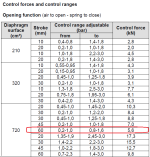
On the nameplate of the pneumatic actuator is written max 6 bar, and in the installation of instrumentation air there is about 5.5 bar. However in the datasheet of the pneumatic actuator, there is so called "control pressure range" and "control force".
I don't understand what this actually means. For example, I have specific actuator with 60 mm full stroke (marked in the attached picture), and it's control range pressure is: from 0.2 up to 1.6 bar.
I don't understand why there is a range in the column "from" and there is a range in the column "to". From: 0.2-1.0 bar and To: 0.8-1.6.
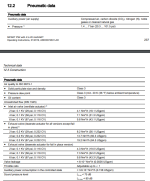
I have Sipart PS 2 positioner, and I'm not sure if I need to order filter pressure reducing valve.
What is confusing to me is the fact that actuator is suitable for max 6 bar, but it's control range is only about 1.5 bar. I'm not sure how to interpret this.
As far as I know, most instrumentation air installations are 6 bar, and SIPART supports up to 7 bar, but pressure range on pneumatic actuator is only 1.5 bar.
I hope there are experts here who can clarify this to me.
Thank you!


