Siemens LOGO! Help....

johnmo85

Member
Join Date
May 2020
Location
UK
Posts
2
Hi All, first post on here looking for help, the site has been a treasure chest full of useful stuff so far during my course work, so thanks a bunch!

I am looking for a little help with my final task of an assessment and looking for anyone who is a handy with FBD building using Siemens LOGO!

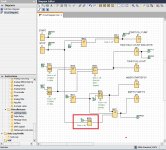
i am about 95% complete on the task but the final function that i need, i just cant get to work properly despite hours of head scratching.

3.png

Essentially, i just need a stop button input for the "empty pump" output, i need this to latch on, and reset when the start button is pressed. i cant seem to do this without messing the rest of the system up. Stop button needs to be able to stop Q1, 3 & 4.

Any help much appreciated!
 
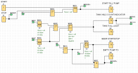
I've downloaded the demo version of the LOGO software and here is my interpretation of your requirement. Posting the complete spec for your tank fill/mix/empty would be better.

logo1.jpg
 
I've downloaded the demo version of the LOGO software and here is my interpretation of your requirement. Posting the complete spec for your tank fill/mix/empty would be better.

Thanks for your help, i actually managed it in the same way you have done, but using the pulse relay instead. I am pretty certain i had tried with the latch relay as you have done but it wouldnt stop the "empty pump" from running as it was supposed to. i am guessing i had something else connected wrong.

fyi.. here was the spec.. (ignore the numbering for the function blocks, im guessing they are what was used by whoever made the assessment paper)

"
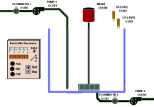
The application above illustrates a simple stirring application in a lemonade factory.

a) Use LOGO to design and build the above system, using function block or ladder logic, which will control the operation as follows:

• When the Start ‘push to make’ (not toggle) switch (I1) is pressed/released, and gets latched on (B1: RS latch), the start ‘fill’ pump (Q1) will be energized and the tank will start to fill.
• The pulses generated by flow meter 1 (B5: pulse generator) should be used to increment the counter (B6: Up/down). Tank level full is when the counter function on = 10 and tank low level is when counter off = 1. These values can be used as feedback to control the pumps (instead of the high/low level sensors shown above) and can be called the ‘tank high/low level count indicator’ (Q5 or use a flag M1)
• When the full liquid level in the tank is sensed by the tank high/low level count indicator (Q5), the fill pump will be shut-off and the FULL light (Q2) on the control panel is to be energized.
• When the tank is full, start the mixer (Q3) and run for 10 seconds (B8: off-delay timer).
• When the 10 seconds has expired, stop the mixer (Q3) and start ‘empty’ pump P3 (Q4).
• Pump 3 (Q4) will be required to run until the tank is empty. Tank empty can be detected using the low-level sensor (I3).
• The pulses generated by flow meter 3 (B15) should be used to decrement the counter (B6: Up/down). Tank empty can be detected by the high/low level count indicator (Q5 or use a flag M1) to switch off the pump
• When the stop button (I2) is operated, the process must stop immediately (Q1, Q3, Q4).

b) Test your LOGO build and comment on your testing using LOGO simulation mode. This requires at least 3 print-screens of testing the system using the LOGO simulator below at the filling, mixing and emptying stages


c) Save your program and email a copy of your program along with your assessment.

Guidance: Clearly snip/print-screen and explain your build and test work. Use input/output (I/Q) numbers shown. Function numbers (B) can be your own choice, and you are also likely to need some basic logic functions (e.g. And/Or/Not) for the various conditions given in 3a. "1.png
 
hi, im currently doing the same bit of coursework and am stuck in a similar position to what you were. did you manage to finish it ? some tips or an image would be very helpful as i cant seem to get the last part of the build to work. The counter stops on 6 and all of the q2, q3, q4, and q5 are on. any help would be appreciated.
 
hi, im currently doing the same bit of coursework and am stuck in a similar position to what you were. did you manage to finish it ? some tips or an image would be very helpful as i cant seem to get the last part of the build to work. The counter stops on 6 and all of the q2, q3, q4, and q5 are on. any help would be appreciated.


Post your work (copy screen image to copy-paste buffer with PrintScreen key; paste into Microsoft Paint, annotate the different functions, save as PNG image; use paper clip
attach.gif
icon in [Go Advanced] posting tool here to select and [Upload] the image), and you might get some comments.
 
Siemens Logo lemonade stirring

Is there any update here? I've tired the diagram like the above image only Q5 switches on! I've tired added different latches with no luck. Thank you
 

Similar Topics

Hi all, First, thank you for reading the thread. So I had a task as the following: An up-counter must be programmed as part of a batch-counting...
Replies
7
Views
280
Hello All, I am using Siemens LOGO!Soft V8 to write a program and am unsure of where the function is fo the CTU as seen in the attached picture...
Replies
6
Views
2,337
Hi, I include a simple program, where an an analogue input switches on Pump 1 and if needed a higher analogue level switches on pump 2. Works...
Replies
7
Views
1,690
Hello, I just bought a LOGO plc in order to learn how to work with it (very new to plc's). I am trying to put it to work, the manual says...
Replies
3
Views
5,698
Hi Lads, I want to implement a flood prevention system with my domestic water pump. The intention is to have the water pump cut off on a daily...
Replies
7
Views
1,065
Back
Top Bottom