Magnetic motor contractor with motor overload - help

backendcode

Member
Join Date
Aug 2017
Location
brampton
Posts
249
Hello Guys,

I am working on my first real world project to control the conveyor system. The control panel has PLC, terminal block for the proximity sensor and motor contactor with motor overload and of course other components of control panel such as power supply, transformer etc and I don't think as a PLC programmer I need to care more about those components.

Question: As a PLC programmer, What factors I need to consider about contractors and motor overload

Here is info about my contractors:-

MOTOR CONTACTOR 10AMPS 24VDC LOW CONSUMPTION COIL 1NO AUXILIARY CONTACT

Here is the info about my motor overload

OVERLOAD RELAY 0.8-1.2A 1NO AND 1NC AUXILIARY CONTACT

The control panel drawing also shows there is feedback going to PLC input card for each motor run and motor overload. Am I going to use the status of those input addresses to find the fault in motor and motor overload and turn on the fault indicator light and stop the light until someone will reset the fault I guess?

What is the purpose of this feedback going to PLC input card and what is the purpose of contractors auxiliary contact (Which is normally open) and auxiliary contact of motor overload(1 NO, 1NC)

Please help me to understand the purpose of this information provided?

Thank you!
 
PLC programmers should know and understand the operations of all components in the system as they ALL can have an effect on the program. I am a controls sparkie first and foremost - I built switch boards, commissioned them, designed old fashioned control circuits when there was no such thing as a PLC, tested, commissioned, lots of service work - broken down machine and no drawing.
Got into PLCs when I had to sell them!
I would suggest you show us what you have done and then you may get back some comments.
No one is going to do your work for you without getting paid lots of $$$$$.
 
Knowing what you are controlling in the field is critical. It will help with understanding what signals you need to send and are receiving, especially when fault finding an installation.

I am relatively new to PLC programming but have been an industrial electrician in manufacturing plants and chemical storage facilities. knowing what to expect from devices at each point of the process has been a huge help to me.

My advice would be to sit down in front of a cabinet with some drawings and figure out what you are looking at and how it works electrically.
 
I have always had an issue with wizz bang programmers that have been to school and have no idea of how a process works to be honest.
I also see designers of critical systems who do not even monitor and alarm critical circuit breakers for example.
24VDC circuit breaker turned off or tripped in a generator system that supplies the trip coils? Ain't gonna work!
Never mind - GOB? (Grumpy old *******).
Most are not taught properly these days and it is better to try and turn hindsight into foresight wherever possible.
 
It's a contactor, not contractor.
On the overload, the NC is wired in series with coil. It prevents operation of the contactor when tripped.

You have two choices for status signals to the PLC. You can use either or both.
The NO contact on the overload can be used to signal the PLC that the overload is tripped.
The NO aux contact is used to indicate status of the contactor. When you energize it, you look for feedback from the aux contact to tell you it really did energize.

Wiring:
PLC output to overload NC contact. Other side to coil +.
24DC to contactor aux. Other side to PLC input. Signal is "Motor is Running".
24DC to Overload NO contact. Other end to PLC input. Signal is "Motor Overload is Tripped". You don't necessarily need this. When you turn on the PLC output to the coil, if it doesn't pull in then you can assume that the overload is tripped.
 
Last edited:
Hello Guys,

I am working on my first real world project to control the conveyor system. The control panel has PLC, terminal block for the proximity sensor and motor contactor with motor overload and of course other components of control panel such as power supply, transformer etc and I don't think as a PLC programmer I need to care more about those components. It's nice to think that those "other components" don't matter to you as a programmer, but you will learn that they are indeed very important to you.

Question: As a PLC programmer, What factors I need to consider about contractors and motor overload
It is really as simple as how and when to pull the starter in, and how and when to release it.

Here is info about my contractors:-

MOTOR CONTACTOR 10AMPS 24VDC LOW CONSUMPTION COIL 1NO AUXILIARY CONTACT

Here is the info about my motor overload

OVERLOAD RELAY 0.8-1.2A 1NO AND 1NC AUXILIARY CONTACT

The control panel drawing also shows there is feedback going to PLC input card for each motor run and motor overload. Am I going to use the status of those input addresses to find the fault in motor and motor overload and turn on the fault indicator light and stop the light until someone will reset the fault I guess?
I would guess so too, but that is really up to the customer as to what sort of feedback and status signals they require.

What is the purpose of this feedback going to PLC input card and what is the purpose of contractors auxiliary contact (Which is normally open) and auxiliary contact of motor overload(1 NO, 1NC)
The purpose of the aux contact on the starter would be so the end user would, through your code, know if the motor is running without having to actually go look at the motor. This same input could be used for the purpose of giving an alarm if the motor is supposed to be running, but isn't.
The contacts on the overloads would serve the same purpose as those on the starter, but give information only about the status of the overloads.


Please help me to understand the purpose of this information provided?
The information was likely provided to give you an idea of what the customer would like in terms of feedback from the starter and the overloads when the project is finished.
I know you want to concentrate on the program, but you might want to get a better handle on the overall scope of the project before writing too much code.


Thank you!


Bubba.
 
Last edited:
I have always had an issue with wizz bang programmers that have been to school and have no idea of how a process works to be honest.
I also see designers of critical systems who do not even monitor and alarm critical circuit breakers for example.
24VDC circuit breaker turned off or tripped in a generator system that supplies the trip coils? Ain't gonna work!
Never mind - GOB? (Grumpy old *******).
Most are not taught properly these days and it is better to try and turn hindsight into foresight wherever possible.

Don't worry, us Bubba's know how to take the wizz out of their bang in a hurry ;)
 
Hello Everyone, Thank you for putting some time in my post. I am going to try my best to replies everyone's concern about my project and forgive me if I forget to mention anyone by mistake in my reply.

So I get an idea from your replies that feedback signal from aux contact of contactor (Not contractor :p) and motor overload to PLC input card will help me to find the state of that component i.e. NO aux contact of contactor will help me to find if contactor is working properly or no and NC/NO aux contact of motor overload will help me to find if my motor is not tripped right?

So quick question, when every time motor will run for a certain amount of time, will my NO feedback signal of AUX contact of contactor become 1 for that period of time or when my motor will not run because of some problem of a contactor, then my NO aux will become 1?
Or in other words, At what condition, NO aux contact of contactor or NO/NC AUX of motor overload will change their state and write 1 or 0 (DEPEND NO OR NC) to the memory address of my PLC input card.


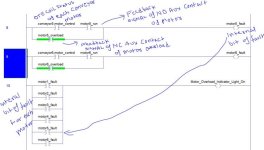
I upload the pic of my PLC code to check the status of those feedback signals to find the fault of the motor and motor overload and if there will be a fault, I am trying to turn on the fault indicator light ON on my control panel.

pic is attached if pic is not clear, I added an external link to that picture so you can have clear idea about it how I am using the feedback signal of those aux contacts to find my motor fault.

https://ibb.co/kHROUQ

Ignore my handwriting on the code but I tried to explain each section of code.


Thank you again!

FINAL_MOTOR_FAULT.jpg
 
PLC programmers should know and understand the operations of all components in the system as they ALL can have an effect on the program. I am a controls sparkie first and foremost - I built switch boards, commissioned them, designed old fashioned control circuits when there was no such thing as a PLC, tested, commissioned, lots of service work - broken down machine and no drawing.
Got into PLCs when I had to sell them!
I would suggest you show us what you have done and then you may get back some comments.
No one is going to do your work for you without getting paid lots of $$$$$.

BobB,
I do agree with you and I am not trying to give you any excuse but there are many people like me who actually want to learn everything about the system they are working on but because of lack of information or mentorship, they may not gain all the information but again these are just an excuses and I am trying my best to learn the control panel components working and trust me this forum and people like you are helping me a lot in my journey!

I uploaded my PLC code, please have a look and give your feedback!

Thank you again!
 
Knowing what you are controlling in the field is critical. It will help with understanding what signals you need to send and are receiving, especially when fault finding an installation.

I am relatively new to PLC programming but have been an industrial electrician in manufacturing plants and chemical storage facilities. knowing what to expect from devices at each point of the process has been a huge help to me.

My advice would be to sit down in front of a cabinet with some drawings and figure out what you are looking at and how it works electrically.

ThatGuy,

I got the drawing and I have a little bit of electronics background and I do understand electricals drawings at some point (No expert but definitely can be one day). I am going to take your advice and may get to know the process of each component with the help of electrician at my work place.

Thank you again!

Cheers!
 
It's a contactor, not contractor.
On the overload, the NC is wired in series with coil. It prevents operation of the contactor when tripped.

You have two choices for status signals to the PLC. You can use either or both.
The NO contact on the overload can be used to signal the PLC that the overload is tripped.
The NO aux contact is used to indicate status of the contactor. When you energize it, you look for feedback from the aux contact to tell you it really did energize.

Wiring:
PLC output to overload NC contact. Other side to coil +.
24DC to contactor aux. Other side to PLC input. Signal is "Motor is Running".
24DC to Overload NO contact. Other end to PLC input. Signal is "Motor Overload is Tripped". You don't necessarily need this. When you turn on the PLC output to the coil, if it doesn't pull in then you can assume that the overload is tripped.

keithkyll, Sorry it was autocorrected of the contactor.

I think I am considering how you mentioned here in this post. Please check my reply with PLC code and what do you think about it.

Thanks!
 
willxfm,

Thank you for pointing out my each question and It was clear and helpfull!

please look at my PLC code I posted in this thread!

Thank you again

The NO aux contacts on the starter will close and remain closed every time the contactor is pulled in. (This is one the things you need to understand about "that other stuff".)

With that in mind take another look at rungs 8 and 9 and see if they are going to work as you intend them to.

Bubba.
 
I am not familiar with few terms here but Let me clear few things here,

You said,
1. A contactor is pulled in - mean current will pass through the contactor or coil of a contactor and produce an electro magnetic fields and energizes the motor?

2. NO aux contacts on the starter will close and remain closed

Means, my AUX contact of starter will always be 1 when the contactor is pulled in and at what condition it will change state or become open? when is the coil not energized or motor is not running?

If I consider the above assumption, here will be my code

Pic attached and link is below

https://ibb.co/fYurik

Thanks again

motor_fault_change.jpg
 
On the motor starter the NC contact on the Overload section is to make sure your motor is running within its rated current. Overloads are sized based on the load the motor will draw.

The NO contact on the Contactor just provides feedback to let you know its pulled in, when it should be.

Its important to correlate what all these inputs mean in the real world when programming.

If this fails -> this is the result

It's critical to understand the possible failure modes relative to each device.
 

Similar Topics

Hi, The hardware is: Click Plc model # CO-O1DD1-O HMI model # S3ML-R magnetic-inductive flow meter model # FMM100-1001. I will set the flow meter...
Replies
4
Views
114
I have a murr IMPACT67 Pro E DIO8 IOL8 M12L 5P and a Magnetic sensor MSA213K. connected to a L18. encoder is connected to port 0 and I am...
Replies
5
Views
614
Hi Experts, I am reading the engine speed from a magnetic pickup - magentic pickup is placed near the flywheel and when a teeth crosses it...
Replies
19
Views
6,093
I need something to vary the speed of a magnetic vibrator. It's 120vac Single Phase, 60HZ, 0.5amp. Need something I could give a 4-20ma signal...
Replies
6
Views
2,184
Hi everyone I have a problem with vfd 3G3-MX2 Omron 1.5KW/2HP/ 3PH. The frecuency driver works fine until another motor start, the other motor is...
Replies
2
Views
2,367
Back
Top Bottom