PanelView 900 to panelbuilder32 connection issues

Yman

Member
Join Date
Oct 2013
Location
IL
Posts
5
Hello All,
I am trying to connect Panel View 900 to my panelbuilder32 software and running into connection issues. Here is what I am using:
Panel View 900 (2711-T9A2)
1747-PIC
25 to 5 pin adapter
Serial cable (no crossover)
Serial gender changer (to be used with the cable)
WindowsXP platform running PanleBuilder32 (Version 03.82.01)
From what I understand in order to communicate (download/upload program) with panelView 900 it (panelview) needs to be connected not only to the programming terminal (PanelBuilder32) but also to the network OR have an AC adapter (1747-NP1) connected to communication port. I figure that is where communication related component’s power for PV900 is coming from thus any network connection should do. PLEASE let me know if that is not the case.
On to the connection:
Network: From PanelView900 to home network switch (cable used – from pv900 “wide” connector (bottom right looking from the back of the PV900) to home “RJ45” regular connecter)
Communication (picture is attached): From PanelView900 (cable used - RJ45 (bottom left plug of PV900 looking form the back) to “wide” connector on the PIC module) to 1747-PIC. From 1747-PIC via ribbon cable (attached to the PIC module) to 25 to 9 pin converter (straight). From 25 to 9 pin converter to 9 pin gender changer. From 9 pin gender changer to serial cable. From serial cable to serial port in the laptop.
Laptop COM port used: there is only one physical COM port in the laptop. I’ve tried renaming the port to COM1, 2 or 3 in device manager, but was unable to connect to panelbuilder32.
When going into the panelbuilder32 and trying to upload a program from PV900 in a “status” window that opens up during the upload I receive the following messages (picture attached):
Info (2018)- Verify your cable connections
Info (2018) – If you are using a direct connection to a PanelView via DF1, insure that the panelview does not have its printer port enabled
Error(2018) – I/O operation did not complete in time.
ON THE PV900 TERMINAL GREEN "COMM" LIGHT IS FLASHING - have not idea what that means.

Please help me out if you can, I’ve been battling this beast for a while now, driving me nuts. Thanks in advance!
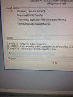
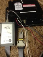
photo 1.jpg photo 2.jpg
 
but also to the network OR have an AC adapter (1747-NP1) connected to communication port. I figure that is where communication related component’s power for PV900 is coming from thus any network connection should do. PLEASE let me know if that is no

You need the above to power the PIC. See PDF for connection diagram.

You need a real serial port to use the PIC. And you need to configure RSLinx for the 1747-PIC/AIC+ driver.

Have you configured RSLinx?

Here is a video for setting up RSLinx. The video talks about Windows XP SP3, if you have that there is a fix for it. Let us know if you need it.

http://www.youtube.com/watch?v=lcIFqImAAzQ

http://plctalk.net/qanda/showthread.php?t=63919
 
Last edited:
Hi Mickey,
Thank you for reply, I think we are starting to get somewhere now. Please see my feedback/clarification below.

"You need the above to power the PIC. See PDF for connection diagram." - will connecting the PV900 to my home network provide adequate power for PIC? Looking at the PDF connection diagram it states to either use the AC adapter (don't have one), or SLC500 network (don't have one) or DH485 network (will my home network qualify as DH485)? Basically trying to avoid buying the AC adapter. I also have micrologix 1100 with a network port, can that be used to power the PIC module? To sum up can I use any of the methods listed below to power my PIC module or do I have to buy the AC adapter:
1. Home network switch running home network
2. Micorologix 1100


"You need a real serial port to use the PIC. And you need to configure RSLinx for the 1747-PIC/AIC+ driver." - got the "real" port on my laptop, no usb converter, nothing of that sort the cable is plugged into the db9 port on the laptop so I think I have that covered.

In regards to RSLinx the answer is NO, I haven't even open RSlinx when trying to make connection between PV900 and panelbuilder software (perhaps that's the issue). Please let me know if I need to go through RSLinx FIRST prior to opening any panelbuilder32 software and trying to make a connection to PV900. If indeed I need to establish the connection between RSlinks and PIC before panelbuilder is open (seems like a logical choice) I will go through the driver update procedure mentioned below and give it a try.

Standing by for your feedback and thank you for your time and efforts in helping me with this endeavor.
 
Apply the brakes !

DH-485 uses a 8-pin modular "RJ-45" jack that looks just like the Ethernet jacks on your home network and your PC, but they are NOT THE SAME.

Some DH-485 devices apply 24V DC power to two of the pins of that jack. The SLC-5/01,02,03 DH485 network ports do this, and the AC adapter that was mentioned in the literature does this. If you connect a powered DH485 port to an Ethernet port on your computer or an Ethernet switch, you will very likely damage the Ethernet port.

What's connected to that other cable that I see on the PanelView ? If that device can provide DH485 power, AND you have a built-in serial port, AND you have a compatible operating system, then MAYBE you can get the RSLinx "1747-PIC/AIC+" driver working and connect to this PanelView terminal.

If the terminal has v3 or later firmware, it is much easier to not use DH485 networking and instead use a PCMCIA memory card. I have had very good luck with SanDisk 2 GB CompactFlash cards in a PCMCIA Type II adapter. There are numerous threads on this Forum describing the exact steps for using those memory cards.
 
Hi Ken,
Thank you for the info on DH485 network (dang I'll have to check if my switch got smoked)! Prior to going out and buying an AC adapter the last thing that I would like to clarify is: can I use my micorlogix 1100 "RJ45" port to "power" the pic module connected to the PV900?

The "other cable" in the picture is the one that i was trying to plug into my network switch to supply "power" to the PIC module. That is obviously incorrect, thus my only options are AC adapter or (if applicable, depending on your reply to above) Micorlogix 1100 "RJ45" port.

Last but not least, do I have to run RSLinx and establish the connection to PIC module prior to trying to work with PV900 and panelbuilder32 software?

Thanks!!

PS
If all else fails I will have to look into alternative means of connection (PCMCA card, etc) however, that process is completely unknown to me thus I will be starting from the scratch (including needed hardware as well, which i don't have)
 
The good news is that your Ethernet switch port is probably fine, because the PanelView terminals don't provide DH485 network power.

The MicroLogix 1100 RJ-45 jack is in fact Ethernet. The MicroLogix 1100 implements DH485 on its Channel 0 (the round 8-pin Mini-DIN plug) serial port, which does not have power pins.

The history of the RJ45 jack is long and boring, but A-B is far from the only vendor who has used it for non-Ethernet connections, both before and after twisted-pair Ethernet became popular in the early 1990s.

I haven't used the PanelBuilder32 built-in drivers in decades. Generally you configure and run RSLinx Classic first, then select "RSLinx Network" as your upload/download path.

CompactFlash cards and adapters are cheap and easy to use. Just verify that your old PanelView has version 3 or later firmware.
 
Ken,
Great, thank you for the info, got it on the RJ45 and Mircologix 1100. Sounds like AC adapter is my only option in this configuration.

I did see RSlinx as an option for connection in panelbuilder32 thus I will try to connect to PIC via RSlinx and then connect PV to panelbuilder via RSLinx network path.

Thank you once again.

PS
How can i verify my PV's version. I assume I have to connect to it first and see it in the settings, OR is there a sticker somewhere. Thanks!
 
There should be a sticker on the back of the terminal that shows the firmware revision number, and it should also appear onscreen at some point during the boot-up process.

The 2711-T9A2 might be one of the very oldest PanelView 900 terminals, with the orange monochrome plasma display. Versions 1 and 2 firmware supported only an old style of PCMCIA flash card called Linear Flash, which are incompatible with modern memory card readers, which use a type of flash memory called ATA.

Version 3 and newer firmware supports both the old Linear Flash and modern ATA Flash cards.
 
Found this on the back sticker "FRN 3.30" I think we're in business (picture attached)! If all good could you please reference me to a post defining required hardware and the procedure on how to connect PV900 via "memory card".

Thanks!!

photo.jpg
 

Similar Topics

Hi, I'm trying to figure out how to properly update the "icons" on my Panelview 900 (AB 2711-T9C9). I think maybe I'm having a fundamental...
Replies
13
Views
985
Panelview 900 communicates with SLC 5/03 PLC. When I upload the program from the panel, some buttons have the address B3/306, B3/304 etc. However...
Replies
9
Views
2,431
Panelview Part #: 2711-K9A8, that communicates via DH+ to a SLC504. There are two PV's on the network. One has lost its application. Downloaded...
Replies
3
Views
1,954
A question for the hive mind, i have a Panelview 900, monochrome non touchscreen model. On power up, i get error 34 which relates to an extended...
Replies
5
Views
2,156
I have those old early 90's panel views in my plant. I use an old XP image to get the program back into them but maintenance wanted a way to do it...
Replies
3
Views
2,378
Back
Top Bottom