Snubber brake on Reliance VFD

Carl Cadieux

Member
Join Date
Sep 2010
Location
Edmonton
Posts
11
I have a GV3000SE VFD with a snubber brake to ramp down. The brake is not working as it should and VFD goes into HV fault if I slow the deceleration too slow for the drive to slow the motor down. Once I correct the problem with the brake I'm wondering if I can add more resistors to assist the existing snubber brake? I believe that when the existing brake was chosen they under rated it because the inertia of a centrifuge is considerable. Any thoughts? I have a spare dynamic brake available that I could add as more resistance.
 
What kind of "HV Fault" ?

If it is overvoltage ("HV" = High Voltage ?), then maybe the brake resistor isnt properly connected. Or you need to change a setting in order to activate the chopper.

If it is overheating of the brake resistor, then yes, adding a seperate brake resistor may well fix it. Have done so (but not on a Reliance VFD though). Follow the instructions for the VFD exactly which resistor to add, and how to do it.
 
Wires are connected correctly. This unit has been in use for over 10 years. Program on VFD could have been changed but I don't see where the snubber brake should be triggered. It is supposed to take up over voltage beyond 750 VDC automatically but is not happening. I don't have a manual to show resistor addition because Reliance was very skimpy on information manual sent with the unit hence the questions.
 
So is the brake not working at all? This could be an indication that the chopper transistor is burnt out.
 
I believe you are correct. The brake is not working at all. Having said this I am hoping that once repaired I can add more resistors to help the unit from overheating and not causing this to occur again. It may even help to remove the existing resistors and replace with extrnal ones to prevent more heat buildup within the brake cabinet.
 
Find out if the brake chopper is integral to the drive or something that is field replaceable, I don't know with a GV3000.

Yes definately get the braking resistors out of the cabinet, unless there is some particular reason to attempt to heat the cabinet, installing the resistors in there is extremely poor practice.

If your brake resistors are still overheating you can add more resistors. The important thing to consider is the resistance the drive sees, you can't go below the drive rating in that regard. You can however add more wattage which will help keep the resistors from overheating.
 
The existing snubber brake is mounted on the outside of a control cabinet where the VFD resides but the resistors are within the box of the snubber brake unit which is physically fairly small. I think that by adding more resistors the unit will not get so hot with external resistors in a separate box.
 
The existing snubber brake is mounted on the outside of a control cabinet where the VFD resides but the resistors are within the box of the snubber brake unit which is physically fairly small. I think that by adding more resistors the unit will not get so hot with external resistors in a separate box.

Carl,

We need you to help us so we can help you. At this point you are our eyes and ears on site. Any wrong information might lead us to the wrong conclusion.

You seem to be concerned about heat in the brake resistor cabinet. Has the heat increased lately? Or has it always ran hot? Does the brake work when it's cold?

Alscott asked about the chopper transistor. We need some info about your unit. What are the terminals that connect the resistor to the drive labeled? How many wires? What is their wire size? With the power disconnected, can you take some continuity checks for us? Is there anything in between the drive and the resistor?

So you are saying there is a "snubber brake unit". Are there controls in the "snubber brake unit"?
 
Last edited:
Let me explain, This equipment (a horizontal centrifuge) has not run for some time (over 1 year). The equipment was put back into process and the operators were having problems slowing the full centrifuge down from 2400 RPM down to 200 rpm. Instead of braking the centrifuge now trips and free wheels due to a HV fault on the VFD.
After runing some tests with the centrifuge empty I found that if I changed the deceleration down to 120 seconds the same thing happens and the brake does not brake at all. I believe the snubber (Rockwell (Reliance) model #2SR41800) is not functioning due to a transistor failure. This still needs to be verified though. The brake is rated for a 20 hp motor (as per the specs) but is braking a 25 HP motor on a centifuge which has alot of inertia to brake. I believe that it was spec'd too small from the beginning and has finally given up. One time (over two years ago) I was able to watch it brake for about 10 seconds then trip out due to over temperature. My question now is: If I repair this snubber brake can I add an extra bank of resistors, to help take up the regenerated energy upon braking? Is the transistor/capacitor set up another limiting factor? Is the right answer to get the correct size brake for the application or can I use what I have now?

DC Buss Terminals on the brake are labeled 3 & 4 and the + & - on the GV3000 VFD. These two wires are about #8 awg wire gauge. There is another two wires for AC supply (460 Volts AC) to the brake termimnals labeled 1 & 2 and come from the main 460 VAC source within the main cabinet. See the url below for what info I have for the snubber. I believe this is wired correctly.

http://www.rockwellautomation.com/relianceelectricdrives/get/D23291.pdf
 
Is the transistor/capacitor set up another limiting factor?

It might be

Is the right answer to get the correct size brake for the application or can I use what I have now?

Right off hand it sounds like you have an extreme braking condition and some oversizing would be needed for a correct fit.

Have you checked the thermal fuse? Just guessing from your description it sounds like the unit runs for a somewhat longish period then it needs to brake severely. This is just a hunch, but I'm guessing in a normal cycle with everything functioning, the cooling fan turns on just as the centrifuge comes to a stop. Presuming a 20 minute to 1 hour period between cycles.

Does the cooling fan work?

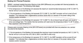
brake.jpg
 
Couple of thoughts. You said it had been working for ten years so whatever has happened is a breakdown. And might be due to undersizing, but the fact you stated it has been working for ten years still needs to be noted.

For braking a load with high inertia you can only do what the motor can do. For example if you have a 25hp motor then that is all the brake you have, regardless of what you do with braking resistors via a chopper. Adding more resistors than the 25hp motor can feed is pointless - it comes down to what the motor can do. Of course oversizing the resistors and chopper is always a good thing, but the limiting factor on braking the high-inertia load still comes down to the motor.

I'll shut up now and let the gurus take it over.
 
I think we need to review the ratings here and it is important to do it in the right sequence.

First, the drive itself has a motoring and a braking horsepower rating. Usually, they are the same. Both are enforced by the current limit trip. So, if you have a 20hp drive and need 30hp of braking, it won't happen.

Assuming the drive is sized properly, the specific model of drive is spec'ed for a particular brake chopper size. This brake chopper will have a specific current limit. Or, rather than a current limit, the chopper may be rated for a particular minimum resistance. It is important to not go under this minimum resistance or you can damage the chopper.

Now, given the minimum brake resistance (which will give you the maximum braking capacity), you need to figure the resistor wattage. If you are slam-stopping a relatively light machine, the brake resistor runs cold and occasionally gets hit with braking energy for a few seconds. Under these conditions, the resistor wattage can be as little as 10% of the actual braking wattage. Unfortunately, stopping a heavy centrifuge is not that kind of situation.

The longer the braking continues, the closer to actual wattage the resistors need to be sized. If the stop is expected to take 120 seconds, you might as well figure full wattage as that is approaching nearly continuous duty. 20hp of braking is 20 x .746kw = 14.92kw so you will need at least 15kw of resistors to keep the heat under control while braking.

So, start with the drive size, find the proper chopper size, find the minimum resistance allowable, and then figure the wattage. That's what you should have. Less than that equals overheated resistors, blown choppers or, if you are lucky, only blown chopper fuses.

Let us know where you end up on this.
 
Thanks guys, I will start with checking the fuses. One thing I recognize is that we are using a 20 HP rated brake for braking a 25 HP motor on a 30 HP VFD. The correct sizing of brake should pobably be the 2ST40075 with external resistors.
 
The correct sizing of brake should pobably be the 2ST40075 with external resistors.

That is what I saw in the PDF you linked to. A couple of things worth noting are.
The max "on" time for your existing model #2SR41800 is 60 seconds and only a 20% duty cycle.

In the 2ST40075 the max "on" time is 120 seconds.

Concerning the fuse I mentioned earlier. On consumer or homeowner grade devices these fuses are soldered or crimped in place, I'm not sure how they are mounted in your device. I saw no other mention of them in the documentation.

I also mentioned earlier the possibility of the fan turning on at near the end of the braking period. What I forgot to also mention is that the fan cooling might have been interrupted, possibly by someone "locking out the power" to the snubber unit before the cooling was finished. This might have allowed the temperature to rise above the 110 C degree limit of the onetime thermal fuse.
 

Similar Topics

I am trying to find a snubber circuit for a relay. I have no clue what to even get I keep looking at rc circuit I found some for sq d relays I...
Replies
9
Views
2,720
The Great Electric Vehicle Project has started. To review Vehicle is a 56 Chev 1/2 ton pickup. I intend to as much as possible ensure truck is...
Replies
29
Views
6,584
i am trying to energize a 26W solinoid coil on a hydraulic valve to run a hydraulic motor to index a conveyor from the my idec micro 1 plc. it's...
Replies
1
Views
2,087
We have an existing VSD where a three phase circuit breaker feeds the drive, and two phases also tee off to a contactor, which is energised to...
Replies
12
Views
1,484
Hey All, I've got a Vacon x4 VFD running in open-vector mode. It is spinning a heavy pin-mill wheel. It gets frequency reference from a PID...
Replies
20
Views
2,537
Back
Top Bottom