PCS7 monitoring fail

userxyz

Member
Join Date
May 2002
Location
any
Posts
2,768
Hi,

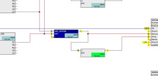
When I monitor in PCS7 I have weird things... input 0 in a NOT function gives 0 at the output, AZND function shows the wrong things... any block... how weird...

pcs7issue.png

Anyone knows the cause of this ?

Thanks,

Kind regards,
Combo
 
From the picture, it looks like you are monitoring OB35, which is a timed cyclic block - meaning it executes at x number of ms, depending on the definition in the CPU Properties. Check what the time value is. Also, without seeing the logic preceding it, it's difficult to tell if there's an issue there.
 
I don't fully know what I am looking at, but whenever I see something like this it is usually because


  • I am re-using an internal bit as the output of multiple blocks and it may have multiple values during each scan.
  • Also when the monitoring program takes a snapshot of the state of that bit it gets only one value.
  • and the monitoring program applies that single value to every display location in the program where that bit appears, regardless of the value of that bit at the the program executed each instruction using that bit.
Stated another way: the monitoring program shows a snapshot of the states of the data; it does not show the states of the program instruction blocks.
 
There is a possibility that the AND block has hidden nubs being addresses by an SFC.
The NOT is confusing. Why not remove the NOT and invert at the Resume block. It appears you have some APL blocks why not use an APL AND also? OB35 is 50 msec cycle, Online usually updates at around 2 seconds, you could be missing the bit changes.
 
Which CFC version are you using?
I guess it has something to do with the little red dot at the 3rd AND input, and also at the Reset input. Maybe it's an interconnection from a SFC as JWR mentioned.


If the CFC chart is not a big one, set the option to generate and keep the SCL source from the chart, and then take a look at the generated code. If you add a unique comment to the AND block, it's relatively easy to locate.
 
If the AND block would have a 4th connection to another block, and then the input is set as invisible, there should be a blue triangle on the top right if the AND block.


If you have an empty 4th input which is set to 0 and then the input set to invisible, you would not see it. I've got only CFC 7 available, maybe they have added a feature to make this visible in newer CFC versions (like signing backwards interconnections). With my CFC version it's also not possible to view the AND inputs with constants 0 or 1.
 

Similar Topics

Does anyone have an example project of the cm ptp ET200 SP HA with 410-5H DCS (PCs7 9.1 SP1) for MODBUS MASTER/SLAVE communication ?
Replies
2
Views
121
Hello, Is there a sequence when installing both TIA Portal and PCS7 in the same PC? First TIA and then PCS7 or viceversa? Thanks in advance.
Replies
0
Views
476
Hello, I'm currently working on a project involving both PCS7 (v9.1 sp2 upd1) and a Panel Comfort system. This necessitates the use of TIA Portal...
Replies
2
Views
780
I'm coming from a background of PLC ladderlogic/rockwell products. I am new to blocks. Can you point me in right right direction? What I would...
Replies
5
Views
1,547
Hello everyone, i would like to read in pcs7 v8.2 the actual day of the month(ex 1 or 25 of the month) i used as attached read_CLK AND DT_DATE but...
Replies
4
Views
1,912
Back
Top Bottom