Lost_Language
Member
Hi All.....First Post here!!
system architecture regarding my question is:
1756-PB72 GuardLogix Processor
1756-L7SP safety Partner
3 x 2 Port 1756-EN2TR Ethernet/IP communication bridge modules
(each module being an independant redundant ring)
Using a point I/O system as children off each independant ring
Now, my job isn't installing or writing software, i basically keep the line running as a technician
i can write a bit and understand a bit and fault find, but not sure how to do the following, or if its even possible to do now the system is in etc.
we were having issues with drop outs and serious lag regarding SCADA terminals etc and ring faults being indicated
I disconnected every ethernet cable and one at a time traced each ethernet cable to determine how things were routed and if there were cross connections within the rings which were meant to be independant (there was)
so I've put it all back together and it is now back to being three independant rings, one for each bridge module.
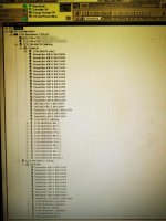
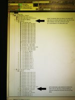
issue now is, as shown in the picture, RACK 00 and RACK 01 which are meant to be part of the "splitting" ring cannot be seen from it.
To enable the splitting ring to see these two racks I've had to put a patch cable bridge between two ethernet switches that each are on either ring (splitting and casting)
this isnt the end of the world but sort of negates the whole point of me trying to get them back to being independant rings.
is there a way i can move RACK 00 and RACK 01 from the casting I/O rung into the splitting I/O rung where it's supposed to be and then i can take out the bridging link between the two switches?
I'm thinking i might not be able to due to the safety being locked and i don't know the password?
Much appreciated for any enlightenment at all if possible


