Problem with Analog PointIO on CompactLogix L18

phuz

Member
Join Date
Jun 2008
Location
Mohnton, PA
Posts
1,044
Sorry for cross posting from MrPLC, but I'm learning there is a lot more traffic here.

I have used PointIO a few times, but this is the first time using an IE4C. The wiring seems pretty straight-forward with Ch0 going to terminal 0 and the common is on terminal 4, if used.
I started off having a solid red status light for the network status, so I changed keying, reset the module, re-seated it and the TB3 base, and finally got a green status light for both, but I am getting ZERO data.
The channel faults are all 0, and the data is all 0, regardless of what I put on the input. I put a simulator between terminals 0 and 4 and the data still doesn't change from 0.

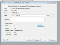
What's more strange is on occasion, I have gone into the IE4C properties and under the Module Info, it would sometimes show Unknown or "Control Techniques PLC" for the vendor. I have seen about 4 different serial numbers appear, and even the revision number has changed. If I hit reset module, it goes back to saying Allen Bradley with the correct serial number and correct revision number, but still does not give any data. I am assuming the module is bad and I have another one en route, but was curious if anyone could explain this because I haven't seen it on any type of module before.


And now, the replacement module has arrived and I am having the EXACT same issue, so unless I am very unlucky and received two bad modules, something else is going on.

These are on the CompactLogix backplane itself, and not on a 1734-AENT.
 
I assume you have checked the box to enable channel 0 in the analog module's input configuration tab. That and assuring proper polarity are all I can imagine with my limited knowledge. Especially if you can read the mA's with a multi-meter in series with the loop as you tested it and are sure of the wiring schematic for the input card.

Good Luck
 
Polarity is fine, and I have put my meter in series with it and it reads my test 12mA.

There is no such thing as Channel 0 enable on the PointIO module. The channels are always enabled.
 
Your initially mentioning that the...

quote... wiring SEEMS pretty straight forward ....unquote

and asking in your reply to Bullzi....

quote.. How do you have yours wired? .. unquote

Points to obvious concern on your part as to the correct wiring..

If you can post a schematic of your wiring and terminals and labeling or even a link to the exact module manual, that may help.

I saw the Mr. PLC input you had as well and the odd figures showing up on channels you.. quote, Are Not Using, unquote.. points to perhaps possible wiring issues? Especially if the numbers on the unused channels are there when you test w/ 12 m.A. and gone when you remove your test current.

I am admittedly a newbie to 5000 and very limited there but have been designing schematics and wiring loops for over 20 years to various components and I believe if you are questioning your wiring, perhaps you should be very specific about what exactly you have wired with a Labeled Drawing showing all connections and how they are connected to the input module and a link to the analog manual wiring diagram.

Just my humble 2 cents.

Good luck
 
No, I am getting erratic numbers despite what is on the channel.
For example right now, there is nothing connected to any of the channels, and the scaling is set for 0-16383 for a 0-20mA input, yet every channel is reading 257 and has a channel fault.

I put my meter in series and connected it to my old Micrologix, and the data shows up fine, and then back over to the IE4C and the data doesn't change.


Can you explain that statement a bit more? Didn't make sense to me...

I am not using an AENT as a remote rack. The L18ER uses PointIO connected directly to the processor, ergo it is right on the CompactLogix backplane.
 
I am just in my 3rd month of Rsogix 5000 and you don't need a newbie throwing spaghetti on your wall. Never having heard of Point I O,( I have a Solo 1769 L23E QBFC1B self made trainer), I hesitate to even reply with this last...
As to point I O, I pulled up a manual, which detailed a round 8 position dial on the mounting base which must be set to the appropriate number depending on the type of module installed before plugging in the module.
No doubt this is "Point I. O. 101" I guess; ASSUMING, [bad word], my manul is similar to your application. I won't waste your time with any more guesses.
I wish you the Best of Luck and, oddly, I thank you for the learning opportunity.

Jeff
 
If it's a 'Series A' controller, do you have 24V field power connected?

From the manual:

Connections to the VDC+ and VDC- terminals do not provide power to input or output devices that are connected to the embedded I/O modules of the controller or local expansion modules. Power must be connected to the FP+ and FP- terminals to provide power to input or output devices that are connected to the embedded I/O modules of the controller or local expansion modules.
 
It could be the TB3 base that is causing the issue. The TB3 is not compatible with all of the point modules.

The IE4C Installation manual says this:

See the figures to familiarize yourself with major parts of the module, noting that the wiring base assembly is one of the following:

• 1734-TB or 1734-TBS POINT I/O two-piece terminal base, which
includes the 1734-RTB removable terminal block and 1734-MB
mounting base

• 1734-TOP or 1734-TOPS POINT I/O one-piece terminal base

The Point I/O selection guide states this for the IE4C:

Terminal Base Unit: 1734-TB, 1734-TBS, 1734-TOP, or 1734-TOPS
 
This could be the problem also:

508507 - CompactLogix 5370 L1 controller incompatible with 1734-IE4C firmware 3.001 modules

Access Level: Everyone
Date Created: 10/09/2012 09:23 AM
Last Updated: 12/01/2014 10:49 AM

Question

Why is the input data static from 1734-IE4C series C in CompactLogix 5370 L1 controller but works fine in 1734-AENT(R) chassis?
Next, here are examples of typical conditions reported:

  • L1 controller I/O status LED is solid green
  • 1734-IE4C module status LEDs appear fine
  • Online no errors are displayed in Controller I/O tree
  • Same 1734-IE4C module works fine when placed in 1734-AENT(R) chassis

Answer

Use 1734-IE4C module with firmware 3.002 or higher when using as local expansion Input module with CompactLogix 5370 L1 controllers.
1734-IE4C series C module firmware 3.001 is not compatible with CompactLogix 5370 L1 controllers.
Note: 1734-IE4C module firmware is not field upgradeable.
 
Yeah, I thought of that but look at page 19 of that manual.
It clearly lists 1734-TB3 as an option.

I am leaning more toward the firmware revision, so let's see.
 
Last edited:

Similar Topics

Hi We're having issues with an FX1N-1DA-BD Analog output module. We're using an metallic contamination sensor MCS 1000 to detect particles. This...
Replies
1
Views
103
Hi, I tried today to get RD3A and WR3A instructions to work on the PLC and it didn't work, but it worked in simulation. I followed the clone...
Replies
18
Views
1,380
Hi, Sorry for my bad english, I'm from Poland. I've decided to learn basic PLC programming as hobby and to maybe get a better job. I have...
Replies
2
Views
1,322
Good evening, just a dump question, I’ve configured channel no 13 with scalling as attached, then shown not linear reading, even when i simulate...
Replies
6
Views
1,700
I have a SLC5/05 with a 1746-NI16V. I am trying to configure it for single ended inputs. Please notice in the screenshot the upper SCP is...
Replies
21
Views
5,480
Back
Top Bottom