Problem with one shot on Modicon

CHIP

Member
Join Date
Oct 2006
Location
Mexico
Posts
11
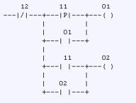
Hello. I have the next diagram in a Modicon 984-381 PLC

12 11 01 |
---|/|---+---|P|---+---( )---|
| | |
| 01 | |
+---| |---+ |
| |
| 11 02 |
+---| |---+---( )---|
| | |
| 02 | |
+---| |---+ |


11 and 12 are push-buttons.

When i activate input 11 the output 01 sometimes actives, other times not.
Output 02 always activates when input 11 is activated.

Any sugestions?
 
Last edited:
Sorry, this is again the ladder diagram

dib.JPG

11 and 12 are push-buttons.

When i activate input 11 the output 01 sometimes actives, other times not.
Output 02 always activates when input 11 is activated.

Any sugestions?
 
I believe that the positive transition passes a TRUE for only one scan if the conditions before it change from false to true. The address associated with it is where the memory of the input conditions are stored.

To make a one-shot of input 11 place a Normally Open contact of input 11 followed by the Positive one-shot with the address of a free bit location. This will be used for this instruction at this particular place only once. Don't use it again in the program.
 
I think that this happens because Modicon scans ladder little bit differently than other PLC's.

Modicon logic is scanned from top left down to right one column, then back up to next column from up to down etc.

On other PLC's scan is from left to right, top to bottom

http://www.plctalk.net/qanda/showthread.php?t=64166

So move rising edge detection of contact 11 to different rung before your old rung as Bernie writed
 
Last edited:
It's not the scan order (which is truly tricky) that I was referring to.

The number above the ']P[' contact is a memory location. It is not an address that the instruction watches to trigger its one-shot output. The input to the one-shot is the logic which exists to its left. When that logic changes from false to true it fires its output for one scan.

For more detail, let's call the bit location referenced above the ']P[' contact as 'M'. On each scan, if the input from the left is TRUE then it examines the value (0 or 1) stored in M. If that stored value is 0 then it outputs to the right a TRUE.

On every scan also (regardless of what it sent out to its right above) it then stores the logic value which was seen on the left into the 'M' location ready to be used as comparison on the next scan.

So to make a one-shot of input 11 write it like this (I'll still refer to the memory location as 'M'):


11 M
----][----------]P[----- ...

 
Pay attention to network scan order (top to bottom, right to left) and coil solve columns. A coil may show in the right most column but it will solve in the column it is placed in. If you are using proworx software there is an option to display the coil in the solve column so turning that on might help you see the problem.

To completely avoid scan issues the solution suggested above needs to be not just on a separate rung but also on a separate network.

However for the logic you posted a positive transition contact isn't necessary. Just use an ordinary contact.
 
The number above the ']P[' contact is a memory location. It is not an address that the instruction watches to trigger its one-shot output. The input to the one-shot is the logic which exists to its left. When that logic changes from false to true it fires its output for one scan.

On Modicon and other telemecanique/Scheider PLC's address above |P| is the address that the one shot inscruction watches.

So on Modicon

--|P|-------------( )

means same as on some PLC's

--| |---|ONS|-------( )
 
Last edited:
The Modicon positive transitional contact works a little differently from what most of us are used to.

The PLC maintains a table of the previous scan state of every 0xxx and 1xxx address. A transitional instruction exclusive ORs the last scan state with the current state and if the XOR is a 1 and the direction (up/down) is right then the transitional contact evaluates true. It does not take into account the state of any preceding logic, so if there is any chance 012 is false then the 011 transition will have no effect on the state of the output since there is no power flow, even if button 011 is held down and 012 subsequently evaluates at true.

I have attached a page from the manual. If you want the entire manual then PM me your email address, its way too big (15mb) to post.
 
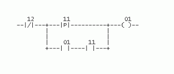
I created the previous rung as a test of the -|P|-

I'm working with a printed copy of an old Modicon program (I use Modsoft), and it's full of rungs like:
dib3.GIF

It's there any way that this rungs work? I have worked with ONS instructions on AB, and I expect that this works similar, but I can't get this to work every time I press 11 (sometimes works, but most times doesn't work)


It does not take into account the state of any preceding logic, so if there is any chance 012 is false then the 011 transition will have no effect on the state of the output since there is no power flow, even if button 011 is held down and 012 subsequently evaluates at true.

12 remains deactivated, and because is a XIO contact, its true and has power flow. I even go further and forced (disabled) by software this bit to avoid any posible electrical interference.


To completely avoid scan issues the solution suggested above needs to be not just on a separate rung but also on a separate network.

Because is a printed copy, I'm not sure the exact spacing between the contacts (if that matters at all). I extended the rung to the right, then put the contacts in diferent columns, but the result is always the same.

I'm thinking that maybe the problem could be related to some scan issues, because it's a very large program (almost using the full 6K of the PLC memory), and with the help of a fast bizarre bouncing of the button, the PLC mark the transition of the contact, but does not allow the power flow...


However for the logic you posted a positive transition contact isn't necessary. Just use an ordinary contact.

Yes, I also think it's overkill. Replacing it with a XIC will do the same. I'm just wondering why was placed originally (and why doesn't work)...
 

Similar Topics

Hi, I am having a challenge installing a new drive ACS355-03E-44A0-4 as it keeps on displaying Fault code F00018 even when the load is not...
Replies
1
Views
61
I have an issue on my vessel, we have water tight door system created in China, company is no longer operating. We have 7 doors each with their...
Replies
3
Views
97
Hi all. Simple as simple can be, I don't understand what's happening. I'm toggling he OSR on, GX_LUB_PUMP1_LEAD should switch. It doesn't. The...
Replies
27
Views
624
Hi; In a cabinet of a machine, a Fatek PLC with an Ethernet communication card is working. In the same cabinet, there is a 1 kW inverter. When...
Replies
16
Views
477
Hello Dear users, I am writing about a problem that has been bothering me for a few days, i.e. I am trying to establish remote access to the Allen...
Replies
0
Views
72
Back
Top Bottom