RS 500 ML1400 - Multiple Modbus TCP Reads & Writes

theColonel26

Lifetime Supporting Member
Join Date
Feb 2014
Location
West Michigan
Posts
785
I need to do 5 reads and 1 write on 2 devices. So that is 10 and 2 total.


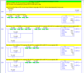
It seems I can't use indirect addressing with MG registers, which is lame. Here is where I am at so far.

Does anyone have any suggestions on making this not an ugly mess? I want to make it easy to add in or remove messages.


See attached

2020-06-22 23-57-05 CL-CTRLS-VM-ROC.jpg
 
Sorry, I can't help on not making this ugly mess..


But your question triggered my memory of a job we did with Modbus messaging - we found out that the rungs with the message instruction could not be edited online - so it may not be easier for you to add in or remove messages o_O
 
I don't know about the MSG instructions, but Rung 0002 stands out as more complex than it needs to be:

xxx.png


Specifically, I am pretty sure that

  1. the [OSR B3:1/0 B3:1/1] can be replaced by [OTE B3:1/1];
  2. beyond that, B3:1/1 is redundant with (will always have an identical value as) C5:30.CU, so that OSR/OTE can be removed, and the [XIO B3:1/1] can be replaced with [XIO C5:30.CU], so B3:1/0 and B3:1/1 are not needed at all.
It's not much of a cleanup, but every little bit helps.
 
I have to do this a lot with Micrologix messaging. I write a ladder file that controls the message trigger bits and put the messages in another file by themselves. Still messy, but if you sweep half the mess under one rug and the other half under another...

The way I do it, the bits that control the messages are written as a mutually exclusive state engine where the DN or ER bit of one message triggers the next message, and if I want to skip a node, there are bits set up to enable/disable the nodes that tie to branches on the rungs driving the state bits. One tip I can give, is that if you want to leave the CHANNEL timeouts at normal values, you will find that your error bits take way too long to go true, but you can manipulate the MTO element of each MG structure to set the timeout to a reasonable number.

I have found that if I manually enter the timeouts I want into the data table, under certain circumstances, the PLC will end up changing them back to crazy high numbers like 30 seconds or greater. I think it is when I perform a download it does this, so in order to enforce my will on the little hardheaded CPU, I will have a startup (first scan) file that writes a value to those timeouts like 3 for hardwired Ethernet messages or as long as 6 for serial radio modems where there are repeaters.

If you just have a timer driving a counter driving your messages, its possible to end up with too many connections for the little Micrologix to deal with...letting the built in timeout do its thing can help greatly with that.
 
I don't know about the MSG instructions, but Rung 0002 stands out as more complex than it needs to be:

View attachment 54817


Specifically, I am pretty sure that

  1. the [OSR B3:1/0 B3:1/1] can be replaced by [OTE B3:1/1];
  2. beyond that, B3:1/1 is redundant with (will always have an identical value as) C5:30.CU, so that OSR/OTE can be removed, and the [XIO B3:1/1] can be replaced with [XIO C5:30.CU], so B3:1/0 and B3:1/1 are not needed at all.
It's not much of a cleanup, but every little bit helps.
Well C5:30 is just being used for debug. I don't want my code to rely on it.


I will look at the OSR and try a OTE.


If you just have a timer driving a counter driving your messages, its possible to end up with too many connections for the little Micrologix to deal with...letting the built in timeout do its thing can help greatly with that.
The intent is that all MSG have mutually exclusive execution like you say. The timer is only used at the end after all messages have been executed and done/errored once. It stops them from executing again immediately. I have it so high (1 second) so I can see what is going on. It will probably be 500ms or 250ms when I am done. If I have some how screwed that up and it is not happening let me know please.


Thanks for the tip on time out. (y)


Not being able to use Indirect addressing On any MG reference is so frustrating I mean I could kinda understand on in the MSG instruction but why the in other instructions. :unsure: It makes no sense that I can think of other than it is Rockwell.
 
Further it seems I do need to unlatch MG Enabled (EN), right? It seems that it stays on and will not run again unless I do that.

I have seen other examples doing it but I am still not sure why. :unsure: Maybe it will make more sense tomorrow.
 
Well C5:30 is just being used for debug. I don't want my code to rely on it.


Got it; I missed that the B3:1/1 rising edge increments the step counter, C5:0, on rung 0.


This is working now, and you are only looking to "clean" things up?


I don't see the need for unlatching the MSG .ENs on Rung 0000; the counter changing value will unlatch those later on each MSG's instruction rung, when each [EQU C5:0.ACC N] goes false.


There might be some advantage to reversing the order of the MSG instruction rungs, so each MSG needs to wait for the next program scan, because you are relying on rising edges.


I don't see the need for the EQUs on each branch of Rung 0002; you are only catching rising edges anyway. [Update: I think I see it now].


It might be possible to somehow combine Rungs 0000 and 0002; a CTU triggers on a rising edge, so sending bits through an OSR, and then feeding that OSR's output (B3:1/1) to counter seems redundant.


I am of two minds on using a counter to keep track of steps in a sequence: if the logic between steps is simple, then it seems cleaner use that logic; if the logic gets too busy then it is worth using a counter or INT. I think this is a case of the former, especially because the transition logic is identical between steps: each MSG instruction is triggered by the .EN OR .ER of the previous MSG's control, can be sealed in by its own .EN, and reset by ORed XIOs on its own .DN and .ER; I think that latter bit only works if the MSG rungs are in reverse order. I'm not sure that will be cleaner though - running an OR of all .ENs and .ERs into one counter, and then having only the EQUs of that counter driving the MSGs, like you have now, might look cleaner.
 
Last edited:
Further it seems I do need to unlatch MG Enabled (EN), right? It seems that it stays on and will not run again unless I do that.

I have seen other examples doing it but I am still not sure why. :unsure: Maybe it will make more sense tomorrow.


wow, it won't run again? I would have thought the [EQU C5:0.ACC N] on each MSG rung would clear each .EN as the sequence step counter (C5:0) advanced to the next step.
 
Last edited:
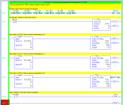
Here is an example without counters; it uses sequential (cascading) timers as proxies for the Colonel's sequential MSGs. It's not very pretty, IMNSHO, but the repeating structure after the first timer is comforting.

xxx.png
Notes

  • Each timer's /DN triggers the next timer
    • The last timer's /DN re-triggers the first
  • Each timer's /EN bit seals-in it operation until expiry
  • Each timer's /DN bit turns it off and resets it /DN bit
  • The timer structures' /DN bits are doubled up wherever they are used because, with the Colonel's MSGs, the control /DN and /ER bits would be used a pair instead
  • Rungs 0000 and 0001 are only there for debugging, and confirm that the sequence of XIOs of the /EN bits occur only once, at the transition into Run mode.
 
The intent is that all MSG have mutually exclusive execution like you say. The timer is only used at the end after all messages have been executed and done/errored once. It stops them from executing again immediately. I have it so high (1 second) so I can see what is going on. It will probably be 500ms or 250ms when I am done. If I have some how screwed that up and it is not happening let me know please.

I may have misread it, and you may have that part right to ensure you don't overflow buffers and connection counts.

Not being able to use Indirect addressing On any MG reference is so frustrating I mean I could kinda understand on in the MSG instruction but why the in other instructions. :unsure: It makes no sense that I can think of other than it is Rockwell.

Yeah, wait til you have 40 messages. You can't even loop through the MTO elements to write them all indirectly...brute force has its own elegance once you have been forced to code that way for a decade or so.

I will attach a shell program that I stripped out all the site specific details from. It has an adjustable "inter-message" delay, measures the total poll time, and includes the state logic to drive the messages and node enable bits all built in.
 
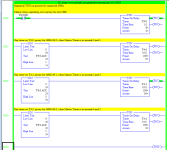
And here is a stripped-down version of the alternate approach i.e. with a sequence step counter.
xxx.png
Again TONs replace MSGs, so the timer /DNs are doubled here as well to emulate the /DN+/ER logic necessary for MSGs; i.e. [XIO T4:0/DN XIO T4:0/DN XIO T4:1/DN...] on Rung 0000 here, with timers, will be [XIO MSG149:0/DN XIO MSG149:0/ER XIO MSG149:1/DN ...] with sequential MSGs.


The negative logic of Rung 0001, using the ANDs of Rung 0001, looks cleaner than the vertical waste of ORing all of the /DNs and /ERs of the MSGs.


Definitely cleaner, IMNSHO (again), but maybe too clever to be easily understood six months hence?
 
Last edited:
And one more idea ...
xxx.png
The focus of the OP's original program seems to be to ensure it does not overlap messages; whether any individual message succeeds (/DN goes to 1) or not (timeout, or /ER goes to 1) does not seem to be critical.


So this approach uses a master timer controlling when MSGs are executed during time slices. The reset at each transition to the next time slice works for the T4:n timers.


That said, I don't know if those resets would clean up internal resources when the time slices are driving MSGs, so this might not be a valid approach for this thread.
 

Similar Topics

I have a Allen Bradely 1500 that has a cracked board. It still works but needs replaced (battery is no longer connected). To make migration easier...
Replies
10
Views
3,222
Hello, I have an AB MicroLogix PLC (1400 1766-L32BWA), and I want to communicate with the SLC500 PLC (1747-L40C) has any of you already done so...
Replies
9
Views
4,276
Hi All. I can write an N7 value to a modbus register in an Automation Direct Servo but I can't read a holding register to an N7 address. I've...
Replies
3
Views
1,899
So I have a device that uses the last 14 bits of a word for the process value. Bit 0 and 1 are used for a different purpose. what is the best...
Replies
7
Views
2,335
Hey guys I created a data filed called N7 for some integers I want to now remove it. Im off line and just working on something at home. RS500...
Replies
3
Views
1,274
Back
Top Bottom