Periodic task and ladder logic structure

bnelson14

Member
Join Date
Jul 2018
Location
Florida
Posts
7
I currently running a compact logix 1769-L33ER 20.11. I have a functioning periodic task that runs every 100ms, using rslogix 5000.

This task is currently bringing in an analog value, doing some conversions and filing a FIFO array to ave then outputting to hmi and control system. It is a total of 9 lines.

Now we are expanding on the project. I am adding 4 more analog values which I need to do the same instances with.

My question is should I create separate periodic tasks or try to arrange all instance in the same periodic task?

I need to execute these analog values the same way to send to the tension system. Guidance to writing the code correctly for better flow and execution would greatly help me learn.

I figured I could created arrays and place all in compact memory locations for like TAGS.
 
I am pretty sure you could collapse that functionality into an AOI, and that have one instance of that AOI for each analog value.


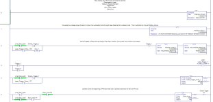
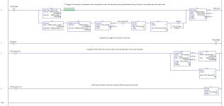
It would help if you could show an image of what the 9 lines look like now.
 
If you plan to have them execute at the same time interval you can certainly add them to the existing periodic task. Just keep in mind that you will be adding scan time to that task so as long as you don't have timing issues with the added logic, you can add the additional code. Of course any time you are adding code, you are adding scan time too.

As drbitboy mentions, if the code is identical, just different analog sources and destinations, you might consider using an Add On Instruction (AOI). If you don't want to use that, you might consider using separate subroutines within the task for each source. Just as a way to keep that logic organized.

OG
 
I have added the ladder in zip and also added images for the code pertaining to my first post.

BTW, the program is running good but I am open to any suggestions.
Thanks.

Ladder pg1.JPG Ladder pg2.JPG
 

Attachments

  • Laser_Logic.zip
    2.4 KB · Views: 6
Last edited:
BTW, the program is running good but I am open to any suggestions..


The CPTs on Rungs 0 and 1 could be replaced with a single SCL, perhaps with the overall formulas in a comment, but the only advantage would be a small increase in performance, and it is understandable to instead have the formulas in the CPTs, especially if occasional re-calibrations may change the constants.


The ONS in the lower branch in Rung 2 is not necessary: the .TT branch on Rung 4 will clear .DN later in the same scan, so the [XIC .DN] in Rung 2 is already a one-shot; the exception, where .DN is not a one-shot, will occur if [XIO Line_Start_Latch XIC Screen_Trigger_1] is true in Rung 4, but that same [XIO...XIC] combination bypasses the .DN/ONS branch in Rung 2 anyway. So the only difference would be an extra scan where the Rung 2 is true past the intial branches and Trigger_1 is 1.


With all the trigger logic, the AOI approach may not be as simple as my earlier glib post suggested, but I think it's still doable.


Still looking at the rest.
 
am I reading this right, that the code waits 5s (5000ms Laser_Trigger_Timer_1.PRE) between writing each analog reading to the FIFO?


Or is that only when the line is not running, and when it is running the cadence is once per 60ms (Scan_Timer.PRE)?


Also, I am a little confused about the intent behind the logic in Rung 5:


xxx.png


Specifically, I am not sure the .TT matters, and in essence I think the four XICs/XIOs at the start could be replaced by a single [XIO Scan_timer.DN].


That said, if the [XIC Line_Start_Latch] starts the timer, after which but before timer expiry the Line_Start_Latch value changes to 0, then the bottom branch will keep the timer going until that expiry, but will not allow it to restart.
 
Last edited:
Clarification

The 5s was added because the laser we are using fills an array from a trigger after a completion of 1 rev. We had an issue where the array would fill with with larger pad diameters during pad installation, giving us the wrong ave value upon machine run mode. So the 5 secs refires the output during the initial startup to give a correct output at the full rev.

I am new to programming so I may have some things causing confusion.

The intention is to scan the analog input into the FIFO of 10 elements, ave them and send to the tension system.
 

Similar Topics

Hello everyone, I am new to PLCs, what will happen if I set the Period of a Periodic task lesser than its execution Time for ControlLogix...
Replies
1
Views
1,655
I've inherited a L61 that was installed last year and the memory usage is well into the red. There is only one continuous task with a scan time of...
Replies
5
Views
3,753
Can this be done based on a pre-selected condition while the PLC is in Run mode? (Logix 5K V20 - Compactlogix L43 CPU)
Replies
17
Views
5,089
Have you ever implemented an event driven periodic task in CLX? How'd you go about it? I have a task that needs to be executed at least every...
Replies
9
Views
2,471
Hi Guys, I've got a problem with a ControlLogix 1756-l61 controller where Watchdog Fault - Periodic task overlap is causing problems. However it...
Replies
15
Views
4,440
Back
Top Bottom