Wrong analog input readings

I then put another 2000lbs in and now, there still reading the same, bout now 2500lbs. I'M BAFFLED! it's 4000lbs of water in the tank.
I have seen a similar problem with a pressure transducer calibrated to read tank level (feet of liquid). These were Rosemont level transmitters, measuring pressure but calibrated at the factory to read a certain range from 0 to X feet. I had 3 tanks of different heights, with 3 different transmitters. The problem was, these were bought used and the maximum height on each was different and none were built for the exact tank height needed.

I had one heck of a job finding a scaling equation for each transmitter that would read the correct level. I finally had to do it the hard way, by emptying the tanks, reading the signal at 0', then filling with water and reading the signal at max height. With the min and max, I could then set up the proper scaling for each tank.
 
Is the tank symmetrical? Is it cylindrical or rectangular? In other words, if you double the volume of water, does the height of the water double as well? If the tank is symmetrical, then pressure should have a linear relationship with the volume of water.

For example: if your tank is cone shaped, then the relationship between the water pressure and volume will not be linear.

I was gonna ask just "What is the shape of the tank?"
 
The problem was, these were bought used and the maximum height on each was different and none were built for the exact tank height needed. I had one heck of a job finding a scaling equation for each transmitter that would read the correct level. I finally had to do it the hard way, by emptying the tanks, reading the signal at 0', then filling with water and reading the signal at max height. With the min and max, I could then set up the proper scaling for each tank.
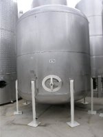
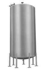
The Upper level in the transmitter is scaled for 61'. The only problem I see is that the cylinder style tank is partially coned at the top and bottom. I measured from bottom weld line to top weld line and it is 61', but what about the section that's coned at the bottom. even though it will most likely read slightly off because of the coned bottom, I don't think it will read that far off. Seems that the more water I put in, the more it reads off (not linear), but the two PLC's are still reading the same now. that sounds like the problem lays in with the pressure transducer. the upper capacity of the tank is 6000lbs. I'm going to fill the tank to the top and scale the transducer to read 60000lbs via the HART communicator and see what I get. I found that calibrating a tanks volume, when possible, that I can calibrate a known capacity of a tank after I fill it to the top and then enter the upper level value via the HART communicator to reflect the same value.
 
Is the tank symmetrical? Is it cylindrical or rectangular?
For example: if your tank is cone shaped, then the relationship between the water pressure and volume will not be linear.

The Upper level in the transmitter is scaled for 61'. The only problem I see is that the cylinder style tank is partially coned at the top and bottom. I measured from bottom weld line to top weld line and it is 61', but what about the section that's coned at the bottom. even though it will most likely read slightly off because of the coned bottom, I don't think it will read that far off, similar to these here...

np79680.jpg bigverticaltank.jpg
 
Last edited:
Aha, that was several thousand words of accurate descriptions you just posted...would have been nice earlier in the thread.

You have a few choices:
Model the tank mathematically and apply that to your transducer reading.
Do a four point calibration, and have three different scale slopes summing as necessary it will get 'cha close with those round coned ends.

Search the forum (not Google, but the good Phil Lemore search) for cone conical tank formula or a mix and match of those words, and open the threads with a significant number of replies. All the answers to this are there.

If you want right now accuracy? Just call the cylindrical part linear and ignore the cones. Then do tests to prove the linearity and measure the responsiveness of the sensor in both directions.

Add the cones later after you wrap your head around the math (which ain't bad at all, but should be added very carefully to a fast scanning PLC program).

Tell the boss, "Yes it's working at 80% tank capacity now, and I will get it to 100 by Tuesday."

EDIT: Also, pull your head out of the forest for a moment and describe the process surrounding the tank application. please.
 
Last edited:
EDIT: Also, pull your head out of the forest for a moment and describe the process surrounding the tank application. please.
it's nothing much around the tank but run tanks one on each side of it. that's it. futher trouble shooting today, i found that when i disconnect the PS leads form the PS +and-, when i read the same wires at the tank they read 20VDC on them, and when the transducer is hooked up it goes down and read 15VDC. so i made a clean run to the transducer. i have my 24VDC the transducer now and still the same votage reading of 15VDC as soon as i hook up the 24VDC coming from the PS, take the + side off-24VDC, connect it-15VDC, take it off-24VDC connect it-15VDC off 24VDC. I went to get a new transducer, hooked up the 24VDC and it stayed 24 VDC while it was hooked up....im going to drain the tank and see if i still have that 15VDC on the tanks transducer, if i do im going to change out the xducer. Question, no mattter what the level of the tank is , the DC voltage should still stay the same correct?
 
>I'm going to fill the tank to the top and scale the transducer to read 60000lbs via the HART communicator and see what I get.

Whoa, stop those ponies ! ! !

The transmitter measures head pressure, not volume, not mass. It measures HEAD PRESSURE. When the medium is water, then a transmitter setup to read in head pressure units of water will also provide a reading in elevation above the center line of the high pressure port. Elevation can then be considered level, when the medium is water (no density compensation needed).

All those words to establish that

1) if the end result that you want to read is pounds, then you need to scale the signal in the PLC/HMI to represent pounds. That involves knowing the tank dimensions and geometry, and knowing exactly the elevation the head pressure is sensed from because a pressure transmitter cannot 'see' head pressure below its own elevation.

2) there is no HART setting to make the transmitter read in pounds. The transmitter reads head pressure and converts it 4-20mA according to its LRV (zero) and URV (span) setting. On some transmitters you can scale the xmtr's local indicator, but that's only the transmitter's local indicator, not the PLC or HMI.

Your efforts to constantly change the wiring amount to chasing electrical non-problems. Your wiring diagram #2 should have worked. Your later wiring change to P/S (+) to xmtr (+), xmtr (-) . . . . was giving a viablesignal, which is all the transmitter can do. The transmitter only give you 4-20ma. It CAN NOT read out in pounds.

If 61 feet of elevation above the transmitter is 6000 pounds of water, you need to
- confirm the transmitter is set to 0-61'
- confirm the transmitter is at zero (not elevated above)
- figure out the scaling for 0 - 6000 pounds
 
the PLC's are already scaled to read for LBS from the head pressure of the transducer. what i found is when i made a clean run (to get rid of that mysterious 20VDC on the signal wire when it was not even connected to the PS) from the PS to the Xducer to the SLC500 and then the PLC5, i got a reading of 4300LBS when the tank was full. My calculations told me that this was a 7000lb tank. i also changed out the bad transducer, the old one kept creating a voltage drop of 9VDC causing no coms with the HART communicator when attempting to calibrate. Once i did that both the SLC and PLC5 scaled simultaneously. The new transducer was giving a 5ma signal output with no pressure on the head, making a reading of 850lbs when the tank was empty, i just went in with the HART and calibrated it to output 4ma at that pressure, to make it output 0.00H20 which in turn read 0lbs at the displays. i also found frayed wires in the old transducers head and changed them out. Now the operators displays from the SLC500 and the PLC5 are reading correctly with the tank filled from 1/4 to 1/2, 3/4 and completely full. GUY's, THANKS FOR EVERYTHING!
 
Last edited:

Similar Topics

Hi all I am having a very weird problem with my control system. I have flex I/O communicating via control net to a RS5000 processor. The analog...
Replies
9
Views
5,725
Hello all, after finishing throwing rotten tomatoes at the screen :D please help me 🤞🏻 . I have a MOSCAD system from Motorola which...
Replies
7
Views
4,150
I am latching and unlatching "result_Data_latch" bit within same rung. Will This copy/move instruction execute correctly??
Replies
4
Views
172
We have a quad monitor setup with FT SE and we are utilizing a header screen at the top of every display. when we open a new page we abort the...
Replies
0
Views
86
Hi all, I am having an issue with FT View Studio ME when I try to open the propoerties of any object, the size of it is very big and doesn't let...
Replies
0
Views
101
Back
Top Bottom