Powerflex 525 Deceleration Rates

Instead of linking to DecelTime3 as you have now, link to DecelTime1. The value you write from the plc in that member will be used as the Decel Time 1 value. the same applies for the accel time. If you do that you won't need to use the BOOLs to select a rate; you just define it directly.

Keith
 
Presumably you're using multiple accel/decel times because you need the drive to accelerate/decelerate at different rates at different times. One way of doing this is to set multiple accel/decel times, and use BOOL logic to have the drive switch between accel/decel 1, 2 and 3 as needed.


Or, you can leave the drive on accel/decel 1 at all times, and instead use the PLC to write different accel/decel times into accel/decel time 1 at the relevant times.


Your statement above though does perhaps offer another hint into what your problem could be. AccelRate1 (and 2 and 3) are INT data type, not BOOL. Those are NOT the tags to select the accel/decel rate, they're the tags where you specify the ramp time. Perhaps you're trying to select accel/decel time 3, and using an OTE addressed to AccelRate 3 to do it? That definitely will give you a data type error - an OTE needs a BOOL tag, and you're giving it an INT tag.


But again -again - this is purely guesswork since you've posted no screenshots or programs and very little other contextual information. I'm about all out of blind guesses, so if you need any more help you'll need to give us something to work with.
 
ASF

You're assumptions are all correct. I am using 3 different rates as I need my hoist/trolley to move accordingly depending on the situation. (automatic, manual, and when hitting a limit switch). And I also did program it to select each rate at the appropriate time. AND I did try to use Deceltime3 as an OTE to select the 3rd rate that I programmed into the drive which caused the error because as you stated it is an INT type.

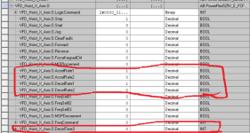
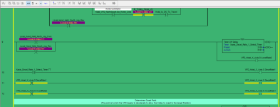
However, I am confused because you stated that accelrate/decelrate 1&2 are also INT type but in my controller tags it shows they are BOOL type and I am using them as such in my logic.(see attached pictures).

Additionally, I see the benefit of using the PLC to write my different times into the accelrate/decelrate1 tag as needed (I was previously unaware that was possible) and plan to program it as such.

But according to my program, as is shown in the pictures, accelrate/decelrate1 are BOOL type. So how would I go about manipulating the time as necessary?

And again, thank you for your help.

tags.png Logic.png
 
Rockwell didn't do you any favors with the tag names they used, but please don't get hung up on the names, which it seems is causing you some heartache.

The tags.AccelRate1, .AccelRate2, .DecelRate1 and .DecelRate2 are NOT accel/decel rates. They are BOOLs used to select the values entered into the .AccelTime# and .DecelTime# parameters in the drive, where # is a value of 1-4. The AccelRate1 and 2 tages DO NOT accept the accel rate value, they SELECT the accel rate value to use from the drive. For example, to select AccelTime4 from the drive you would set the BOOLs .AccelRate1 and AcccelRate2.

The other way to approach this is the make sure the BOOLs .AccelRate1 and .AccelRate2 are both set to OFF as well as DecelRate1 and DecelRate2. This selects the AccelTime1 and DecelTime1 values in the drive. Then directly write your desired accel and decel times in the .AccelTime1 and .DecelTime1 INT values in the drive. To do this you need to set datalinks in the output image to .AccelTime1 and .DecelTime1, just like you do with .DecelTime3. In fact, you can get rid of .DecelTim3 since you won't need it.

Keith
 
There we go. A picture speaks 1000 words!

AccelRate1 and AccelRate2 as you say are BOOL tags, which you turn on or off to select whether the drive uses AccelTime1 or AccelTime2. I now understand that you are using the PLC to switch between AccelTime1 and AccelTime2, which are fixed times, programmed into the VSD, by writing a one or a zero to the AccelRate1 and AccelRate2 BOOL tags.

You have then tried to enable the selection of AccelTime3, which is again a fixed time programmed into the drive. However, after following the advice you received, you added a datalink which gave you access to AccelTime3, not AccelRate3.

So, where to from here? I'm not sure of a way to get the AccelRate3 BOOL tag into the PLC over ethernet. It may not be possible without getting into some in-depth explicit messaging. The reason for this (if it is indeed the case)is likely because it's far simpler to do what I described previously - dynamically change your AccelTime in the PLC, rather than having two or three fixed AccelTime's and using two or three AccelRate's to select them.

So, my advice would be:
1. Record the values for AccelTime1, 2 and 3 from the VSD parameters. For this example, let's assume that the times are 1000ms, 5000ms, and 8000ms respectively.
2. Find the PLC logic that sets the OTE's for AccelRate1, AccelRate2 and your work-in-progress AccelRate3
3. Change the datalink in your drive setup from AccelTime3 to AccelTime1
4. Modify the logic so that where AccelRate1 was previously selected, you now instead simply move 1000ms (or whatever) into AccelTime1
5. Modify the logic so that where AccelRate2 was previously selected, you now instead simply move 5000ms (or whatever) into AccelTime1
5. Modify the logic so that where AccelRate3 was previously selected, you now instead simply move 8000ms (or whatever) into AccelTime1
6. Modify the logic to so that the drive always uses AccelTime1 (e.g. unconditional OTE addressed to AccelRate1)
7. Repeat for Decel tags
8. ???
9. Profit!

Two notes:
1. Make sure when you change the datalink in your VSD setup within the PLC, that you also change the respective VSD parameter to match
2. The value you send to the VSD for the ramp time is not in milliseconds. Some scaling will be required, e.g. divide by 10 or multiply by 10. I can't remember the exact figures off the top of my head - it's something I set up once a long time ago in an AOI and have never had to look at again. Easiest way to work it out is to just send a test value e.g. 12345 down to the drive and see how it shows up in the drive, then adjust your scaling accordingly.
 
Last edited:

Similar Topics

Hi to all. We need to change a bad powerFlex 525 to a new one. How do you save the configuration to install in the new one? Thank you all for...
Replies
5
Views
214
Im trying to teach a couple of labs on VFDs at a community college. We have some motor control trainers with P525s and 3 phase motors from...
Replies
2
Views
220
New to vfds. I put in parameters. IP, but I get ethernet flashing and link solid. What did I do wrong?
Replies
9
Views
450
Are the N files in the 525 the same as the 40p for ethernet? (E-Comm card) I have used 40P with Micrologix 1400 Messaging but don't see the N...
Replies
4
Views
220
Hey all, I am currently working on a depalletizer for a customer and we are doing a hoist upgrade. This is a SLC500 processor and the drives are...
Replies
6
Views
284
Back
Top Bottom