quick question about indirect addressing in rslogix 500

TL140

Lifetime Supporting Member
Join Date
Jun 2014
Location
South Carolina
Posts
152
when your pointer gets indexed, if your previous reference is true, and your current reference is true before getting indexed, will the instruction being addressed see a true to false to true transition?
 
No. At least if I understand your question correctly.

Let's say you have this rung:
Code:
|    B3:0/[N7:0]    B3:1/0     B3:1/2
|--------| |---------[ONS]------(  )-|

Assuming that N7:0 changes from 0 to 1, and that both B3:0/0 and B3:0/1 are true at all times...

Scan 1, N7:0 = 0
1. Is B3:0/0 true? Yes, so the rung-out condition is true.
2. Rung-in condition to ONS instruction is true. Is the memory bit in B3:1/0 true? No, so the rung-out condition of the ONS instruction is true, as is the memory bit of the ONS (B3:1/0)
3. Rung-in condition to the OTE instruction is true, so B3:1/1 is set to true

Scan 2, N7:0 = 0 (no change)
1. Is B3:0/0 true? Yes, so the rung-out condition is true.
2. Rung-in condition to ONS instruction is true. Is the memory bit in B3:1/0 true? Yes, so the rung-out condition of the ONS instruction is false. The memory bit of the ONS (B3:1/0) remains true as the rung-in condition to the OTE is true
3. Rung-in condition to the OTE instruction is false, so B3:1/1 is set to false

Scan 2, N7:0 = 1
1. Is B3:0/1 true? Yes, so the rung-out condition is true.
2. Rung-in condition to ONS instruction is true. Is the memory bit in B3:1/0 true? Yes, so the rung-out condition of the ONS instruction is false. The memory bit of the ONS (B3:1/0) remains true as the rung-in condition to the OTE is true
3. Rung-in condition to the OTE instruction is false, so B3:1/1 is set to false

With this type of question it's more accurate to think about each instruction in terms of rung-in and rung-out conditions, rather than true or false. The XIC instruction is evaluated on it's current merits each scan, and the PLC never "looks ahead" to see if it needs to change anything now that a certain value has changed. It just executes the code, one line at a time, in exactly the situation it finds it at that moment.
 
If you want to force a false for one scan you could set a bit on when the pointer integer changes, than add a XIO [that_bit] before the OSR and it would be off that scan and reset the OSR storage bit
 
Would I have to make a compare statement comparing previous int vs new int or is there an easier way?

Also, is there an easy way to tell a total of how many bits are on in a B3 word? Right now I'm having a 1ms pulse on a counter indexing through that word connected to a counter
 
Would I have to make a compare statement comparing previous int vs new int or is there an easier way?
That's probably the easiest way. In Logix 5000 there is a "DTR" instruction (Data TRansition) which is designed to do exactly this, but (a) I don't think it's available for RSLogix 500, and (b) I've never used it because in my opinion it's no simpler than a NEQ-MOV pair anyway.

Also, is there an easy way to tell a total of how many bits are on in a B3 word? Right now I'm having a 1ms pulse on a counter indexing through that word connected to a counter

Hmm. That's a good one.

You could brute force it several different ways.

You could use a pointer and a loop to count them.

You could copy the B3 word to another word, and use a bit shift instruction 16 times, counting how many 1's drop off the end.

Ultimately, none of them (as far as I can see) are any significant improvement on what you're currently doing.

I once did a similar thing on a reject system. There was a camera system inspecting about 40 widgets per second and rejecting the bad ones into a bin. One day, a widget got stuck in the trackwork, not enough to block the widget flow, but just enough to damage all of the other widgets as they went past. 40 widgets per second went flooding into the widget reject bin, which very quickly disappeared under a mountain of widgets.

Following that, I was asked to put in some logic so that if any more than 25 of the last 100 widgets were rejected, the line stopped before we created another widget-alanche. I used the bit shift method, where a 1 represented a rejected widget, and a 0 represented a passed widget. It worked well - I was using an old Quantum PLC, not an AB, but the instructions I used would probably translate across. Where this differs to your method is that I was counting the 1's being shifted in as well as out, rather than your case of 1's just being there or not, and being counted in situ. So it may not be the best approach for you.
 
Thanks for the response. Right now I'm revamping an old college project so I will have something to take to interviews. Its an automated horse feeder. I'm implementing an HMI and on the HMI there's a horse "check in" bit word. I have just a simple seal in circuit to show if there is a horse in that particular stable on a config screen. 8 stables in total. I needed a total amount of horses to use that in the math so I can evenly distribute the feed to each particular stable. motor rotates a unit until its in position, a line vac comes on and fills the trough.

First time working with indirect addressing but the concept is actually pretty easy for me to understand. I've tried on emulator and the counting seems to work. I may use your BSL method. I'll definitely have to use the transition method you spoke of too. getting caught up in the instance that if 2 or more consecutive stables are empty, no transition is made to move to the appropriate position or 2 positions over.
 
...on the HMI there's a horse "check in" bit word.

Now there's a sentence I didn't expect to read today :ROFLMAO:

Sounds great! Without knowing the full story, you could look at making it a bit simpler by not worrying about where the horses are ahead of time. If you've counted the horses and know how many there are, and how much feed to distribute to each one, then just run your motor without worrying about where it's going. Each time it arrives at a stall, check for "horse present" (another sentence I didn't think I'd read today). If there's a horse there, stop and dispense your calculated amount of feed. If not, continue on. Rinse and repeat.
 
There's Counting bits set bits Brian Kernighan's way. You'll have to convert C into ladder and it's a bit more obscure but it is capable of operating faster than the straight counting methods.
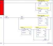
...which is basically by the sounds of it, more or less what the OP is currently doing (although one scan at a time, with a 1ms pulse, instead of all in one scan).

Here's what Brian's method looks like in Logix 500 ladder. It might be "simpler" in terms of less instructions than other options, but it is as Doug says a little more obscure. And I'm going to disagree with Doug in that I would bet a carton of Australia's finest Pale Ale that a brute force solution would execute faster than any of the other solutions we've thrown up so far 🍻

Screen Shot 2017-08-15 at 1.38.08 pm.jpg
 
...which is basically by the sounds of it, more or less what the OP is currently doing (although one scan at a time, with a 1ms pulse, instead of all in one scan).

Here's what Brian's method looks like in Logix 500 ladder. It might be "simpler" in terms of less instructions than other options, but it is as Doug says a little more obscure. And I'm going to disagree with Doug in that I would bet a carton of Australia's finest Pale Ale that a brute force solution would execute faster than any of the other solutions we've thrown up so far 🍻

Just took a look at the code and its almost identical except for the LBL/JMP. Also at work so I couldn't view that site so thanks for the pic.
 
Here's what Brian's method looks like in Logix 500 ladder.
I came up with a different interpretation. Paste this code into Logix 500 to see what it looks like - it's a bit tall to comfortably fit on one screenful. Note that the code for the third rung extends past the window boundary.

N7:0 = argument, N7:1 = accumulator

Code:
GRT N7:0 0 ONS B3:0/4 BST CLR N7:1 NXB OTL B3:0/1 BND
MOV N7:1 N7:1
LBL 1 XIC B3:0/1 BST ADD N7:1 1 N7:1 NXB BST SUB N7:0 1 N7:2 NXB AND N7:0 N7:2 N7:0 NXB XIO S:0/2 JMP 1 BND BND
OTU B3:0/1
 
Wow! That's quite an interesting way of doing it. Side note: I couldn't get your link to work either, so I just googled the guy's name and looked at his theory on stack exchange. So we might be looking at a different source code to base our ladder logic equivalents off.

Your version would definitely work, and I don't want to make out that I'm being dismissive, but there are a LOT of options I'd go through before getting to that one. The processor math zero flag is a neat trick, but seems like a very processor-specific solution. And you're right about it being obscure - looking at that there's no way at all I'd be able to guess what it was meant to be achieving, I'd have to work it through with some examples to see what the results were. I suppose that's why we have rung comments :D
 
Side note: I couldn't get your link to work either, so I just googled the guy's name and looked at his theory on stack exchange.
My error. I was trying save those interested having to sift through the site to find that one item and didn't test the link before posting. For future reference, here's the link to the main page of Bit Twiddling hacks. Something nags at me that it was Peter Nachtwey who first mentioned it here.
The processor math zero flag is a neat trick, but seems like a very processor-specific solution.
Agreed. But, where available it does save a few clock cycles.

:site:
 

Similar Topics

So the quick and short of the situation is that I designed an axle press that was sent to one of my company's other facilities. That facility just...
Replies
19
Views
4,178
So I have a PID loop on an 1756-L61 running V17 software just for background. Also the PID PV is a pressure transmitter and the CV is speed sent...
Replies
1
Views
892
Has anyone come across a 3 turn potentiometer that is panal mounted with either a 22 or 30 mm hole? I have been looking but nothing so far. They...
Replies
20
Views
4,657
Hi, I am just learning CCW, finally got connected to a micro820. I'm wondering what the Version number means. The program that was already in the...
Replies
1
Views
1,608
How do I measure if I am getting a signal out of the plc output? All of the outputs are giving me the same voltage, however I am certain that not...
Replies
6
Views
2,163
Back
Top Bottom