Ge fanuc & micrologix 1400 modbus comms

driverx

Member
Join Date
Mar 2021
Location
quebec
Posts
52
Hello everybody,
I want to communicate with two PLCs (PC1: GE Fanuc: proficy machine edition which runs under quick panel IC754C & PLC2: Microlgix 1400 1766-L32BWA),
to do the communication I added the PROSOFT interface (PLX31-EIT-MBTCP -EtherNet/IP to Modbus TCP/IP-)
because the communication Protocol of PC1 is MODBUS and PLC2 is ethernet IP.
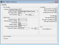
I want to read registers from PC1 to PLC2. to do this I used the Msg instruction (see MSG image), I have no error but I do not receive any value, all the values are zero, even if I change the value of the INT tags and the states contacts and coil on the PC1 side
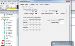
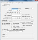
here is the configuration I made for PLC2: (see PLC2 image)
the IP addresse of PC1: 10.1.51.102
PLC2: 10.1.51.103
PROSOFT: 10.1.51.101
pinging ip addresse is good for all three.
msg.JPG plc2_image1.JPG plc2_image2.JPG
 
Are you sure the Quick Panel Control unit is set up as a Modbus TCP server? Your use of the MSG instruction implies to me that you want the MicroLogix to be the client.
I've never used the ladder logic engine on a Quick Panel Control unit, but if you can post a backup of the project file I'll take a look to see if i can spot anything.
 
Please clarify that you are using a QuickPanel HMI with a "PLC" control unit on it, not just configuring a QuickPanel to serve as the HMI for a MicroLogix controller.

The MicroLogix 1400 Series B does support Modbus/TCP natively. There should be no need for a Prosoft network gateway device in this system.

Even if the Prosoft gateway was set up correctly, you're sending Modbus/TCP requests to it, not EtherNet/IP A-B style MicroLogix Data Table Read requests, so it is probably properly responding with the values in its Modbus/TCP register memory area.

I think you are mixing up the functionality of the Prosoft device, as well as the MSG instruction ("client") and the Modbus/TCP data table register mapping ("server") features of the MicroLogix 1400.
 
Last edited:
the quickpanel we are using is HMI & control at same time.only a remote I/O is connected to the quickpanel. there is no PLC .
i succed to read data from the quickpanel but i don't know where is located the data in GE Proficy. because it doesn't show the (reference view table).
where are the modbus data located in windows?
thank you.
 
If you want the Quick Panel to act as a Modbus TCP server to the MicroLogix client, add a "Modbus Slave" to the list of Control I/O drivers and set it up for Modbus TCP instead of the default serial connection. Once you have done that you can map traditional Modbus addresses (4xxxx, 3xxxx, 1xxxx, 0xxxx) to your project's variables.
 
Last edited:
I want to read registers from PC1 [fanuc] to [by?] PLC2 [1400]. to do this I used the Msg instruction (see MSG image),


The second and third image attachments in the OP are not relevant if the 1400 is using the MSG to do a Modbus client read from the fanuc. The [X] Modbus TCP Enable checkbox in plc_image1.JPG and everything in plc_image2.JPG configure the 1400 to be a Modbus server. E.g. see this video. That is unlikely to prevent the 1400 from being a Modbus client using that MSG instruction (attachment msg.JPG), but neither are they necessary.

How has the GE fanuc been configured to be a Modbus server? That is usually where you configure the mapping from Modbus registers to data in the Modbus server i.e. in the GE fanuc.

[I see @Steve Bailey got there before me].
 
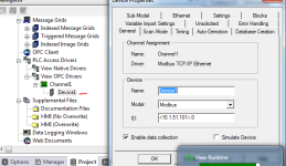
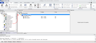
Hi , Thanks for your help, i created an opc server in the GE Fanuc quickPanel ,

to send data to the clien .

my probleme is tha mapping tags adresses ?

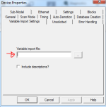
I exported the variables to file .csv and import it in modbus window to

autgenarate the tags ref.

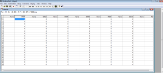
in the prosoft or the modbus Poll software for test. i can see the

communication is good but data are all in 0 , even the values in GE Fanuc

Quickpanel are defferent fron 0.

tha file .txt is not working well, the tag adresse are not good.

i don't know how toCapture1.PNG

Capture2.PNG
 
The OPC driver you show is going to be the device that initiates communications (client). If you want the MicroLogix to be in control of the communications, which is what the MSG instruction does, you need to set up the Quick Panel to be a server.
The communications devices you set up in the "PLC Access Drivers" section of the menu tree are all going to be clients. To set up a server, go to the "Control I/O drivers" menu tree item and add a "Modbus Slave" driver. It will default to serial communications (Modbus RTU) but you can change that to ethernet (Modbus TCP). That is where you map the variables in your project to Modbus addresses.
If your employer will permit, post you project file here and I'll try to guide you through what you need to do. If your employer won't let you post it, perhaps they will let you send a backup to me directly. In that case send me a private message and I'll give you my email address.
 
Last edited:
thanks, my company don't allow exchange data ,
but a created the modbus driver as a slave and map tags ,
but i canot communicate using the modbus poll sofware .
check images.
 
Based on the screenshot, the attempt to download to the Quick Panel failed. Or did you correct the error and successfully download later?


----------------------------------------------------------------------

yes you have right, i tried again and the download is done this time.
but i have problem on reading modbus.
picture attached.

Capture6.PNG
 
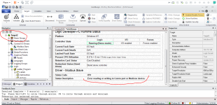
It looks like you created a new target, Target2. Is your Modbus slave setup in Target2 the same as for Target1? Because error code 851 suggests you left the I/O driver as serial. I base that on the fact that there is an error code 854: Error reading or writing to Ethernet port or Modicon device.
Edit: The arrows in your diagram are in the opposite direction to what I have been assuming you are trying to accomplish. My assumption was based on your use of the MSG instruction in the MicroLogix.
Edit2: Well, maybe not. Here's what I think you're trying to do. The MicroLogix is sending a read holding register request to the Quick Panel asking for the contents of modbus address 40001, or 40002, or both.
 
Last edited:

Similar Topics

Distance between this two plcs is 2 km How i can share 4 anolog & 8 digital signal on 2 way communication . I am using Indusoft SCADA with...
Replies
0
Views
3,434
I have a CNC cutting equipment, all the components are Fanuc from the CNC CPU A02B-0307-B822, a PLC AIF01A and a panel i, on the panel i (operator...
Replies
1
Views
105
I want to buy this program if anyone has it. Absolutely no one has it officially for sale. My cpu is IC610CPU104B My mail...
Replies
2
Views
108
I've got a Micrologix 1100 with ethernet and I'm trying to configure communications to a Fanuc R30iB controller. I'm pretty sure you have to set...
Replies
0
Views
99
We recently purchased a IC693CPU352 module and it appears the internal time clock is static. I can set the time and date but once set it does not...
Replies
5
Views
168
Back
Top Bottom