Logix PID timing question

elfrider

Member
Join Date
Nov 2015
Location
Midlands
Posts
30
Hi all,

I'm trying to fully understand the different effects of the Loop Update Time parameter within the Logix PID instruction.

I was always under the belief that you should code the PID instruction in a periodic task, and set the PID Loop Update Time parameter to match the interval of the periodic task.

The reason I ask is that after upgrading an L32E CPU to an L33ER, and migrating the logic, the PID is now acting MUCH less aggressively than it was before. All setpoints have been transferred over exactly the same - the only difference is the old CPU had the PID in a Continuous task, with a Loop Update time of 2 seconds set. The new CPU is the same, except the PID is now in a periodic task set to 2 seconds (and a Loop Update of 2 seconds also).

My interpretation must be wrong, as either the old PID was executing much quicker than every 2 seconds, or the new one is executing much slower than every 2 seconds? What actually is the best practice? How do I ensure a migration that retains the exact same operation without fail? Why is the advice to use a periodic task AND the Loop Update Time, why not one or the other?

Thanks.
 
based on what you've posted so far, smart money says that the PID (as originally located in the continuous task) was executing (being triggered) once on every processor scan ... (something like several hundred times a second) ...

IMPORTANT! ... with the RSLogix5000 platform, the Loop Update Time does NOT affect how often the PID gets executed ... note: that same rule doesn't always apply to the RSLogix500 platform – but that's another story ...

anyway ... now that you've moved the PID into a periodic task, the PID is being executed/triggered on a MUCH slower schedule – so somehow or another, you've got to "retune" it to these new operating conditions ...

the following link about Bubba's paycheck might help you understand the ideas – even though it was written for another platform ...

http://www.plctalk.net/qanda/showthread.php?p=73610&postcount=10

now then ... just as an EXPERIMENT (not a proper "fix") you might try putting the PID right back into the continuous task – and see how close it comes to working ... note that this procedure shouldn't be considered a permanent correction – but it might get you back in operation if you're in trouble with a system that suddenly isn't working at all ... something like the boss saying: "Well, it was working FINE – before you FIXED it." ...

good luck with it ...
 
Last edited:
Thanks Ron.

What you say definitely supports what’s happening. It begs the question what was the purpose of the Loop Update time in the old CPU if the result was it was still executed every scan?

If I were to now simply move the PID into a Continuous Task as before, I am right in saying it’s likely to execute faster than before due to the faster scan time of the new CPU?

In a nutshell do I need to therefore start again with the tuning process?
 
I am slightly surprised that the conversion of your code from the old controller to a new controller actually changed the code or the structure of the program !!

If a PID instruction was in the continuous task before, why would a controller change suddenly put it into a periodic task ? Perhaps RA has introduced rational thinking and AI.... I guess not !!
 
Thanks Ron.

1. What you say definitely supports what’s happening. It begs the question what was the purpose of the Loop Update time in the old CPU if the result was it was still executed every scan?

2. If I were to now simply move the PID into a Continuous Task as before, I am right in saying it’s likely to execute faster than before due to the faster scan time of the new CPU?

3. In a nutshell do I need to therefore start again with the tuning process?

3. In a nutshell yes. If you have an estimate of the old mean scan time, you can start by adjusting Ki (up) and Kd (down), or Ti (down) and Td (up) by the ratio of that old scan time to 2s

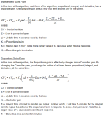
Just for curiosity, what were the tuning parameters (Ki or Ti and Kd or Td), also what form of PID was configured? I suspect the parameters were extreme: Ki will be low or Ti will be high; Kd will be high or Td will be low; both effects compensate for the actual Δt compared to the Δt used in the instruction; see image below. Kp/Kc *might* be close, to first order, but there could be some sampling issues.

2. Yes it may be too aggressive in the continuous task if the mean scan time of the new continuous task is significantly faster i.e. the (actual Δt/declared update Δt) ratio will be more extreme.

1. Even though the implementation was (perhaps*) wrong, the purpose of the update time was to supply a, wrong, but non-zero positive number, for Δt in the formulae below; the fact that it was wrong did not matter in the end because the time-dependent tuning constants were likely adjusted to compensate for the wrong-ness factor, and the mean scan time was probably consistent enough. Also, since the update time was 2s, this is not a fast loop, and any noise in the scan time would have disappeared over longer periods i.e. hundreds or thousands of scans.

* Caveat: even if the PID was in the continuous task, if it was only executed on the expiration of a self-repeating two-second timer, it would be roughly correct, and any variation in the timer's period would almost certainly disappear over a 2s+/-small ms interval.

xxx.png
 
Last edited:
My apologies I should have made it clearer, it wasn’t merely a conversion but a rewrite to more up to date ladder conventions as required by the customer, however the PID operates with the exact same parameters (other than being moved into a periodic task).

Reading further, it is clear that the Loop Update time parameter is the programmer telling the instruction at what rate it is being executed. I guess my question is, what is the effect of setting this wrong? It is clear that the old code was wrong in that it had the PID being executed every scan (continuous task) with an Loop Update Time set to 2 seconds, but what actual effect does doing this have? What does it actually use that parameter for?

The math(s) executed in the PID instruction are based on time, rate of change etc., they need to know what has changed since the last calculations, and needs to know how long (time) has elapsed. Without the UPD parameter matching the execution rate, all hell is broke loose !
 
Thanks drbitboy, I’m getting closer to understanding the effect of the Update time parameter.

The Kp was 2 and the Ki was 5000 which did strike me as a very high (slow acting) value, however I put this down to the fact the process is a very slow responding one. So yes it looks like the original installer did compensate for the overly fast scan rate with the setting of these.
 
So I guess the scan rate determines how often the maths is calculated, and the Update Time is our way of telling the PID instruction this. If these aren’t the same then the maths becomes screwed. So based on this, if I put one PID instruction in a 1 second periodic task with a 1 second Update Time, and another in a 2 second periodic task with a 2 second Update Time, the two PID’s would calculated identically?
 
Thanks drbitboy, I’m getting closer to understanding the effect of the Update time parameter.

The Kp was 2 and the Ki was 5000 which did strike me as a very high (slow acting) value, however I put this down to the fact the process is a very slow responding one. So yes it looks like the original installer did compensate for the overly fast scan rate with the setting of these.


You got it !

Compensating for the faster scan by fiddling the parameters ....

I believe the PIDE instruction uses the controllers clock to actually measure the elapsed time since the last execution, which takes account of any bad programming practices ...
 
So I guess the scan rate determines how often the maths is calculated, and the Update Time is our way of telling the PID instruction this. If these aren’t the same then the maths becomes screwed. So based on this, if I put one PID instruction in a 1 second periodic task with a 1 second Update Time, and another in a 2 second periodic task with a 2 second Update Time, the two PID’s would calculated identically?


Yes
 
I guess my question is, what is the effect of setting this wrong? It is clear that the old code was wrong in that it had the PID being executed every scan (continuous task) with an Loop Update Time set to 2 seconds, but what actual effect does doing this have? What does it actually use that parameter for?


Look at the Independent Gains form of the PID:

xxx.png

The change from update to update, (CVn - CVn-1), is calculated by the PID instruction as
Kp ΔE + Ci E + Cd ((ΔEn - ΔEn-1) - (ΔEn-1 - ΔEn-2))

Now, if we say that this loop is well-behaved with
Ci = Ki Δt / 60
Cd = Kd 60 / Δt
Δt = the old actual Δt update time i.e. continuous scan time on the old system
Ki = the Ki entered into the PID configuration on the old system
Kd = the Kd entered into the PID configuration on the old system

Since Ki, Kd, and 60 are all constant, and mean Δt is more or less constant, from PID update to update, Ci and Cd are also constant. So as long as Ci and Cd are the same in the new system with PID in a 2s periodic scan, as they were for the old system with the PID executing every scan in the continuous scan, for a slow-moving process the overall performance of the PID will be about the same.


[Hmm, I think there may be summat amiss in that logic, but I'll leave it out there and see if someone else sees the flaw.]
 
Ki was 5000 which did strike me as a very high (slow acting) value


That is probably Ti = 5000 (Dependent form) instead of Ki (Independent form).


I'll bet two bits that a Ti of 5 will work well with the PID in the two-second periodic task.


And my last post is baloney.
 
To put things into perspective, on a large brewery job I was involved in, we knew there would be in excess of 20 PID control loops, but phased in as the job progressed.

What we did was to put the loops into a periodic task but we spread the execution of the PIDs using a cyclic counter, so as not to overload the periodic task each trigger.

We had (for example, I can't remember detail) a periodic task of 20mS, and we executed 5 PIDs based on the periodic task count. The PID execution rate was therefore 100mS, but spread like butter.

As the job progressed, we introduced more and more PIDs, and we never had to adjust PID terms in the loops we had already commissioned.
 

Similar Topics

Hello all, I'm having issues with a PID and trying to tune it. I just do not understand why my CV goes to 105 with the settings I have. Config...
Replies
14
Views
1,569
Hello, I have a flow control PID that keeps locking up. It seems to control fine but after a while the output no longer moves. For instance...
Replies
4
Views
961
Hello all! First official post here... have been using the site for help but managed to find existing threads to help with all previous issues...
Replies
8
Views
1,202
Hi, Long time not in the forum, and not in the programming. I´m getting back. I was issued a conversion from RSLogix 500 to RSLogix 5000 (studio...
Replies
0
Views
1,287
So I have a PID loop on an 1756-L61 running V17 software just for background. Also the PID PV is a pressure transmitter and the CV is speed sent...
Replies
1
Views
893
Back
Top Bottom