Toshiba EX100 Programming Access Help

The programming port is located on the CPU Module PU11A (EX10-MPU11A), not on the EX10-MCL11 module.

Yes, thank you for clarifying that. :D

I apologize for any confusion. I thought my question was clear within the context of my previous post. Now that I've read it again, I see that didn't convey my intent. Let me clarify.

My reference to the connections on page 4 of the EXPDD manual 520 applies to the computer link that is built into an enhanced CPU (PU12A). It appears that the computer link is passive not active. Since they are both on the same CPU and you can program from either, I was asking if they both used the same type of current loop. When I stated "what is the programming port", my intent was to ask if the programming port is passive too. It should have read, What is the programming port, active or passive?

I hope this clears things up a bit. Once again I apologize for the confusion.
 
Last edited:
I made a print of the pinout for the EX100 PU-11A programming port. I believe the mating connector is FCN-361P008 although I may have to use FCN-364P008 due to availability. I still have to test and see if the programming port is active or passive. I am expecting it to be passive however I may be wrong since the manual for the DP100 and HP100 shows they use 5v which it is provided by the CPU. I suspect the B&B 232CL9R current loop converter will work. If the programming port is passive I hope to use the CPU 5v power supply instead of the 12v listed in the B&B literature. I plan to try the same connection as shown for the CA67 cable.

Thank you jrwb4gbm for all your help. Thank you for suggesting the HP100 was powered by the CPU. Thank you also for finding the Current loop converter and CA67 cable information. You have been a tremendous help.

EX100_Pinout.jpg
 
Last edited:
Here is a current loop converter schematic. If you can't buy one like you need, maybe you can build one using this schematic. I don't know if it will work or not. Use at your own risk.
See attached file.
 
Wow, thank you jrwb4gbm! (y) Many thanks! I never could of gotten this far without your help! Once I get it hooked up I'll let you know how it works. Thanks again!
dale
 
I ordered all the parts from Mouser. They got here Friday so now I'm working on getting it ready to test. I decided to build it on a breadboard to try it out. I couldn't get the right connector for the EX100 programming port so I ordered the PCB mount connector. I'm having some difficulty adapting it to a cable end connector. I soldered it to a circuit board for support and still have to add some wires. Hopefully I'll be testing it out in the next few days. Building electronics is new to me, I actually had to look up on the web how to use a breadboard. Not having experience has me concerned something might go wrong. I'm praying I get it right the first time and don't damage the CPU or loose the programming. I wish I had another CPU to try it out on.
 
COOL! I was able to purchase a used EX100 rack off ebay for a reasonable price to test out the programming cable. I just couldn't bring myself to test out the current loop on the only copy of the ladder logic. Hopefully I can sell some of the parts to the customer for spares to recoup the purchase. When the CPU gets here I should be ready for testing!
 
For older plcs such as this, it is always a good idea for the customer to have spares, especially some that have been field tested. Hang in there, you'll get this project working.
 
For older plcs such as this, it is always a good idea for the customer to have spares, especially some that have been field tested. Hang in there, you'll get this project working.

Yeah, the customer has no spares. When I first started this project one of the employees had just replaced some cables that were damaged and the servo motor. I had to replace both EX10-MPI21 cards and the servo amplifier. Not having the ladder logic, it took a while to diagnose. With both cards bad it was difficult because I tried to swap them with each other for diagnostic purposes and I was swapping problems. Shortly after I replaced them the servo drive failed. I found a used servo drive installed it and built an interface cable to tune it. Even after tuning the servo amp, there are still some quirks that need addressing. The PLC doesn't always recognize the machine is in position. I think it can be corrected by opening the trigger window in the ladder logic. If not it will sure help me having the ladder logic and access to the CPU to diagnose the problem.

The thing that concerns me the most and I highly suspect may have caused the failures, is the high line voltage into the building. It is over 500 volts so by the time it is transformed down to 240 and 120 I have 260 and 130, and sometimes slightly over that. Right at the threshold of over-voltage! I think a buck boost transformer is the answer although I've never dealt with one before, so I'm reading up about them too.
 
Last edited:
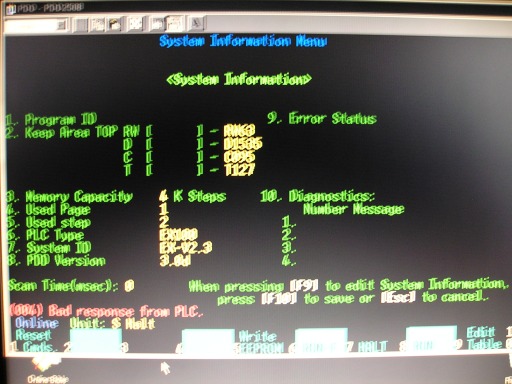
Well, I completed the programming cable and hooked it up to the used EX100 Rack off of ebay. I am able to access the PLC via EXPDD ver3 however I keep getting the following error: "(004) Bad response from PLC". I suspect either the CPU is bad or the programming cable isn't quite right. I built the programming adapter circuit on a breadboard so I'm wondering if there might be an intermittent connection causing the problem. I tried to save the programming and got the same error, however the ladder logic only contains 1 line which is "end". This unit was installed with a Panel-tec MT-200 and I think the programming was stored in it. Maybe that has something to do with my error? I think the next step is to figure out how to program this thing and try to upload something.

P1010057_sm.jpg
 
It certainly appears that your interface is working based on the picture.

Here is a link to a similar PLC software manual (EXPDD2040). It is for the EX20/40 series.
Link:
http://www.toshiba.com/ind/data/tag_files/EXPDD2040%20Manual_510.pdf

The command tree begins on page 95. From the screen shown in the picture, press F1 to access the Reset Commands. Page 27 in the manual has more details. Since it is just a test PLC, try them all. Maybe one of them will clear the error (004). The list of error messages begins on page 99.
 
Last edited:
Yeah! :D Thank you jrwb4gbm! (y) The interface works! My problem was the programming port mating connector. It was making intermittent contact which caused the error. Once I got it corrected I had no problem accessing the ladder logic via the PDD v3 software. I can save it but I don't have anyway to open or print it out with out a hardware key. :( I think I can edit it online, however I really need a print out to follow the logic and locate where the problem is.

Does anyone have the capability to print the ladder logic out for me?🤞🏻
 
Wow! Finally got it going. Congratulations! Zip and post the files. There may be more than one. I'm sure someone can print them out to a pdf or text type file.
 
I'm not sure I got a good save of the program sine one of the files is 0 bytes. I can't open it to find out and since I can't open it I certainly can't print it which is what I need at this point. Any help would be greatly appreciated. Thank you in advance.

Click here for the program.
 
There are no device names, that probably accounts for the 0 byte file. If you have a drawing for the machine with the wiring to the PLC maybe I could go thru it and label the inputs and outputs.
See attached file:
 
I'm not sure I got a good save of the program since one of the files is 0 bytes. I can't open it to find out and since I can't open it I certainly can't print it which is what I need at this point. Any help would be greatly appreciated. Thank you in advance.

Click here for the program.

The Save was Good. The attached file shows how to Open the program Offline and do a Print workaround. This is without using a Hardware Key. You can use this procedure to create the text ladder file like in my last post. It's a slow, tedious procedure for large programs.
 

Similar Topics

Hi I'm having a bit of trouble finding a programmming cable for a toshiba EX100. None left with toshiba according to our suppliers. Can anyone...
Replies
7
Views
9,041
We are using Toshiba ex100 plc. Please kindly suggest how to connect to the plc programming port via EXPDD250 software (version 3). I know that i...
Replies
7
Views
13,217
Another software thread! We have a Toshiba EX100 that's just been working away quietly in a panel for 20 years, never causing a problem to...
Replies
1
Views
1,198
Hi, does anybody know if a HMI can be used with an old Toshiba EX100 PLC and if so which one? I cannot find any driver in the E-Designer software...
Replies
4
Views
1,661
We have a few machines here that have Toshiba EX100 PLCs in them. I found a programming cable with hardware dongle on Ebay. I am getting a no...
Replies
13
Views
5,253
Back
Top Bottom