Angular to Linear Motion Speed Control

Daniel_LeRoy

Lifetime Supporting Member
Join Date
May 2011
Location
USA
Posts
103
Hello Everyone!

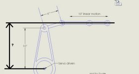
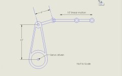
I have a motion application I need some help with. Here is a sketch:
vCNzMlt


I need to be able to control the speed of the linear motion in feet per second, and I am having trouble with the math. I have tried searching through here and I know its possible.

The linear motion just goes back and forth and need to be able to adjust the speed on the fly.

I am using an AllenBradley 5069-L330ERM with Mitsubishi J4-TM servos.

Thanks in advance!
drawing.jpg
 
What is the missing dimension or is it chosen so there is exactly 10 inches of linear motion?

crank.jpg
 
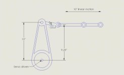
That dimension is 9.25" The sketch is not 100%, i just whipped that up to illustrate the motion. I have updated it to be slightly more accurate.

I realize when it comes time, the dimensions will be highly critical, and they will be exact in the end. I just want to make sure this is possible, or we will come up with a different solution.

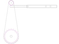
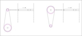
drawing 2.jpg
 
Last edited:
Note the max and min position of the linear motion vice versa the servo position.
Take the differences and apply it to the mechanical gear ratio on the servo parameter setting.
If you can get the linear position correctly, the speed is just the matter at setting it to what you want.
 
I know a math free way of doing this.
Move the linear motion links in approximately 0.5 inch increments. At each increment record the angle or encoder position of the servo driven arm. Put this in a cam table or what we call a curve table so the servo arm arm position is y and the linear motion is x.
Now you can issue commands to the axis in linear motion axis and the linear position will index into the curve to find the servo arm's position. Since we compute the first and second derivatives and apply the chain rule the velocity and acceleration will be accurate too.

We use this trick all the time to linearize motion without math.
http://deltamotion.com/peter/NewHydraulicTrainingSystems/Basic and Hammer.mp4
This is a video of our advanced training class. The second system is our "system from hell"
The hammer is given postion, speed and acceleration commands in degrees. There is a curve that converts the degrees to linear motion for the hydraulic actuator. We even use the degrees to index in to curves that have the controller gains as a function of angle so the motion is always smooth.

The trick is using the chain rule. Do you remember that from calculus?
 
Google "slider rocker function" but I suspect implemention will be the tricky part. If a kinetic servo was used it would be a lot simpler using the cam motion instructions with a cam profile as Peter has pointed out. Hopefully cam profiles can be created in the Mitsubishi drive.
 
Thank you for all the replies. I have done some serious googling and the math still boggles my mind. o_O

I think the cam (curve) table is the way to go for us. Thank you Peter for your suggestion. I am going to keep diving into this and do some experimenting.

Osman, yes a rack and pinion would probably be easier mechanical solution, but for this particular instance the servo would be an easier package physically... we may have to go to that route, we will see.

thanks again.
 
1) It looks to me like you will have a tough time getting 10" linear motion out of the linkage. There is some additional info needed. How is the horizontal section constrained? What limits the angular motion? Is the horizontal link above (1st sketch) or below (2nd sketch) the arm's top pivot at top dead center.

2) To obtain uniform linear velocity you need non-uniform angular velocity.

3) This cries out for a graphical solution. You appear to have access to CAD. Draw the linkage to scale, showing the linear position of the slide corresponding to each angular position of the arm. Then you can plot it in Excell and develop a relationship.

Tom, plotting to excel is a great idea. The horizontal motion is below the top arm pivot when the arm is at 12 o'clock. The horizontal section is not constrained its on a linear rail with space to spare. The servo motor will limit the angular motion.
 

Similar Topics

Any one know iso 1438 open channel Rectangular notch discharge equation
Replies
1
Views
1,578
Good Afternoon , I just finished a project using Rockwell SensaGuard Safety Sensors. I keep getting random faults …… Red Flashing LED ...
Replies
0
Views
1,127
Would anyone know of an HMI software package that allows angular fill of an object? I was wanting to set up a circular gauge 0-360*, but was...
Replies
15
Views
4,159
I need a couple of European style rectangular connectors for an application that will require 80 pins each, mixed discrete and analog, plus I'd...
Replies
6
Views
2,434
Who do you purchase your rectangular connectors from? I have used Phoenix Contact Heavycon and Lapp USA connectors.
Replies
5
Views
2,323
Back
Top Bottom