Addresses needed for Micrologix 1400 built-in analogs

wildcatherder

Member
Join Date
May 2009
Location
Morro Bay
Posts
168
This is another one of those basic bits of information that does not seem to be readily available.đź““

What are the addresses for the built-in analog inputs and outputs for a Micrologix 1400 (for models that have analog capability)?

I found a post that said the inputs should be I:0.4 and I:0.5 which I would like to confirm.

I could find nothing about addresses for the built-in analog outputs?

Would someone please direct me to this information?

I have searched through the Micrologix 1400 User Manual without finding this little bit of info.
 
From manual 1766-rm001_-en-p.pdf page 32

The MicroLogix 1400 -L32BWAA, -L32AWAA, and -L32BXBA support
2-channel, 12-bit resolution analog output. These channels have 0…10V
DC output range. Output words 4 and 5 contain the value of analog
outputs (Word 4 : analog output channel 0, Word 5 : analog output
channel 1).
 
Thank you. That is exactly what I needed to know.

The Analog Outputs are on page 32:
...support 2-channel, 12-bit resolution analog output... Output words 4 and 5 contain the value of analog outputs (Word 4: analog output channel 0, Word 5: analog output channel 1).

This is another one of those documents doubtless included in my DVD of Technical Documentation which has yet to arrive.

The link to the "Instruction Set Reference Manual" is invaluable and more appreciated than just providing the answer to the one questions.

Thanks again.
 
I am also struggling to find a suitable address for the analog inputs for the 4 used on the 1400, the Instruction set referencece manual is a bit vague on that.
 
I am also struggling to find a suitable address for the analog inputs for the 4 used on the 1400, the Instruction set referencece manual is a bit vague on that.

I:0.4 input 0
I:0.5 input 1
I:0.6 input 2
I:0.7 input 3

0 volts = 0 raw data
10 volts = 4095 raw data

See picture

analogaddresses.jpg
 
Last edited:
analogs

Thanks for your reply, I have already assigned those addresses to expansion I/O and cannot at present figure an alternative. (I am using I or O;0 through 7. Unless it is possible to re-assign the expansion modules, which I have already written the code for.
 
I have already assigned those addresses to expansion I/O and cannot at present figure an alternative.

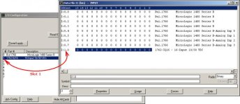
not 100% sure how you're setting up your system hardware ... but ... I think that you'll find that your "expansion I/O" (once properly added to your I/O Configuration) will have addresses with SLOT NUMBERS which are NOT zero ...

.

slot1.jpg
 
which I have already written the code for.

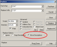
if you've done a LOT of work already using incorrect address assignments, the following tool might be helpful to you ... look under Search/Replace - and notice that you can use wildcards ...

SUGGESTION: play around with a SPARE copy of your program to see how this works - and you have to be "offline" to use it ...

good luck with your project ...

.

replace.PNG
 
Thanks for your reply, I have already assigned those addresses to expansion I/O and cannot at present figure an alternative. (I am using I or O;0 through 7. Unless it is possible to re-assign the expansion modules, which I have already written the code for.

The addresses I posted are for the embedded I/O analog inputs. They cannot be assigned or reassigned.

What is the complete catalog number of your ML1400?
 
IT IS THE 1766-L32BXBA, tried your suggestion with search/replace, which re-assigns ok, but I think when I reassign I;7/0 - I;7/3 to I;7/4 - I;7/7 respectively, I cannot configure the I;7/0 etc, for my analog input.
I have an input module in slot 7, which I think cold be the problem with 4 I/p's used. I may have to add a 4 channel analog module to the project.
 
the BIT addresses that you're giving don't "line up" with "analog inputs" ... (where is the SEVEN coming from?) ...

your best bet is to post your ENTIRE .RSS file (even if it's wrong) ... zip it first - forum rule ... once we see that, we can help you with detailed answers ...
 
Last edited:
I:7/0, I:7/1, I:7/2, I:7/3, I:7/4, I:7/5, I:7/6, I:7/7 are all bit addresses.

I have an input module in slot 7

Is it an analog or digital input module?

If analog then use addresses below.

I:7.0, I;7.1, I:7.2, I:7.3, I:7.4, I:7.5, I:7.6, I:7.7 are word addresses.

Use the word addresses for your analog input data.

Can you post the program its .RSS file? (zip it first.)

EDIT: Ron types faster then I do.
 
Last edited:

Similar Topics

Hello to all, Is it possible to export Codesys symbols to .txt, .csv or .xml in a similar manner like exporting symbol table in STEP 7? For...
Replies
0
Views
120
Hi guys, so I'm using BOOTP/DHCP tool in my virtual machine for setting up an IP addresses for basically everything. My only issue is always with...
Replies
3
Views
355
Hi. I'm doing an upgrade of an old 1400e to a new panel view plus 7 standard using ftv studio v 12,which will be communicating to a slc 5/04 via...
Replies
15
Views
2,606
Trying to find the proper documentation to explain the CC-Link Parameters for Mitsubishi remote I/O. The system I am modifying uses several...
Replies
0
Views
344
Besides using BootP in the past, I am relatively new to having to look for privately addressed devices in many control networks. All of the...
Replies
23
Views
3,868
Back
Top Bottom