Level Sensor

joaco1993

Lifetime Supporting Member
Join Date
Sep 2014
Location
newyork
Posts
237
Im installing a level sensor and cannot get it to work. this is the sensor:

https://cache.industry.siemens.com/dl/files/141/45351141/att_5659/v1/7ML19985KQ01.pdf

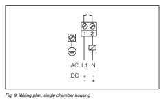
In terminal 1 I have connected +24Vdc and in terminal 2 the plc input, however when I put the sensor under water or product the signal never changes, I always measure the same voltaje between terminal 1 and 2. However the light changes from green to red..

What could be the problem ??

I saw that the datasheet says this, what does it mean that is not suitable for low voltaje plc input ?? that it wont work ? why ??

Warning:
The instrument must not be operated without an intermediately
connected load, because the electronics would be destroyed if
connected directly to the mains. It is not suitable for connection
to low voltage PLC inputs.
For direct control of relays, contactors, magnet valves, warning
lights, horns etc.
Domestic current is temporarily lowered below 1 mA after
switching off the load so that contactors, whose holding current
is lower than the constant domestic current of the electronics,
are reliably switched off.

Thanks in advance !!
 
We use this type for run dry protection

"I always measure the same voltaje between terminal 1 and 2. However the light changes from green to red.."

Which is the correct condition

See figure 6.3

When the tuning forks contact the medium, then the switch turns off and the light goes red.
 
The lights of the sensor works correctly, it is used for high level switch, so when there is no product, the contact is closed and with product it opens.

However I dont see a change in the input voltaje when there is product and when there is not..

And if the contact is closed the voltaje between 1 and 2 should be 0 , it must have the same voltaje if its just a contact and its closed..

Dont get it why I meassure 14V if its closed the contact
 
Last edited:
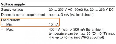
The device uses 3 ma to power it. So when the level switch is 'open', it is not open, but still letting 3 ma current through it. This is enough current that the PLC input still sees the switch as closed. The device is made for powering solenoids, not PLC inputs. If you want to use it as an input to the PLC, you will put a resistor across your PLC input terminals. It needs to have low enough resistance that 3 ma current produces a voltage lower than the turn on voltage for your input card. It need to be of a big enough wattage to be able to handle the current that it will draw when the level switch closes and you get 24V to the resistor and the input point.
 
Ok steve that could be a problem, I will try putting an interposing relay.

However how do you explain this ?

However I dont see a change in the input voltaje when there is product and when there is not..

And if the contact is closed the voltaje between 1 and 2 should be 0 , it must have the same voltaje if its just a contact and its closed..

Dont get it why I meassure 14V if its closed the contact, shouldnt I see 0V between 1 and 2 if the contact is closed.. ??
 
Ok steve that could be a problem, I will try putting an interposing relay.

However how do you explain this ?
It's a solid state device with some leakage current that exceeds what is required by the input point.

And if the contact is closed the voltaje between 1 and 2 should be 0 , it must have the same voltaje if its just a contact and its closed..

Dont get it why I meassure 14V if its closed the contact, shouldnt I see 0V between 1 and 2 if the contact is closed.. ??

It's not a contact, it is a transistor. EDIT: or triac.
 
Last edited:
The device uses 3 ma to power it. So when the level switch is 'open', it is not open, but still letting 3 ma current through it. This is enough current that the PLC input still sees the switch as closed. The device is made for powering solenoids, not PLC inputs. If you want to use it as an input to the PLC, you will put a resistor across your PLC input terminals. It needs to have low enough resistance that 3 ma current produces a voltage lower than the turn on voltage for your input card. It need to be of a big enough wattage to be able to handle the current that it will draw when the level switch closes and you get 24V to the resistor and the input point.

Proof I dont get it..

If product reaches the sensor the contact will open and no current will flow as it doesnt have a return path.. how does it still power the lights ??

Im missing something
 
Okie is a contactless electronic switch,

That is just another way to say solid state. It might not be a TRIAC, it could be a SSR. This spec shows a universal supply voltage. Put a load on it that falls between the minimum and maximum load current and you will see the output voltage behave more like a switch.

fork sensor leakage.jpg
 
Proof I dont get it..

If product reaches the sensor the contact will open and no current will flow as it doesnt have a return path.. how does it still power the lights ??

Im missing something

It doesn't have a contact, it has adjusts it resistance. If it had a contact that opened, no current would flow, but then it would have any power flowing through it, and it wouldn't be able to power the electronics that it uses to sense the level, or turn on the led lights. This device always has some current flowing through it, and that is why the PLC shows the output as On. The output is On when the level is low, and On more when the level is high!

PLC inputs have fairly high input impedance. They let a little current flow through them so that very small currents (noise) will get drained, and will not produce a voltage across the inputs. When full signal voltage is applied (like through a contact), the high impedance in the input card keeps the input from drawing large currents, wasting power, and heating up the input cards.
 
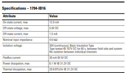
Ok let me see If im getting this. The module im using is the folowing: 1794 ib16

which has an input impedance of 4600 ohm , so if 24Vdc is applied a current of 5mA will flow, which is not enough to get the sensor for working as it says minimum 10mA. But has enough current to turn on the lights ( more than 3mA)

So if I put a resistor of 1000ohm between the input and the common ( that would be like in parralel to the input impedance) I would have like 30mA in total and that would let the sensor work correctly right ??

Or another solution would be to put interposing relays right ?

Thanks for the help guys

ssss.png
 
Ok let me see If im getting this. The module im using is the folowing: 1794 ib16

which has an input impedance of 4600 ohm , so if 24Vdc is applied a current of 5mA will flow, which is not enough to get the sensor for working as it says minimum 10mA. But has enough current to turn on the lights ( more than 3mA)

So if I put a resistor of 1000ohm between the input and the common ( that would be like in parralel to the input impedance) I would have like 30mA in total and that would let the sensor work correctly right ??

Or another solution would be to put interposing relays right ?

Thanks for the help guys

A resistor or a relay should work as long as it pulls enough power.
 
Even with an interposing relay, a resistor for min load in parallell could be required. Had that before. Interposing relay going "trtrtrtrtrtrtrtrtrtrtrtr" in off position.
 
yep you are right, the relay has an impedance of 16kohm so definetly I will have to put a resistor in paralel in order to get +10mA.

Now the only thing that is still ticking my head is why the lights work properly ?? they work in a different circuit ??

I mean when there is no product, light is green and when there is product light goes red..
 

Similar Topics

how to program a laser level sensor to a cooler tank with an AB plc
Replies
6
Views
1,312
Hey guys, We have a metal container at work, we fill with saw dust (20fts x 15fts x 10fts) with the top open but we normally put a container...
Replies
4
Views
1,543
Hi everyone; Im having some problems with a digital level capacitive sensor. I wired it in the NO configuration and the input of the digital...
Replies
8
Views
3,409
Hello everyone, I need to install a level sensor in an existing plastic tank. It will go on top and there will not be pressure on it except if...
Replies
14
Views
7,318
Hello, I'm looking for a float style temp/level analog transmitter (0-10V analog) for a water tank. There are no chemicals in the water but the...
Replies
3
Views
1,671
Back
Top Bottom