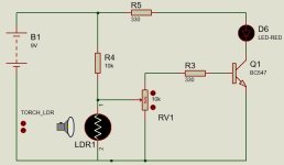
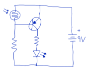
Ok, I understand that circuit of post 13 will not work as I will need a transistor. I am still unable to solve this. On the last circuit I posted, when measuring with the virtual instruments of the Proteus simulator I can see a very low voltage at the connection point to the PLC but in real life I measure between about 5 and 12V. As I am using all the other inputs of the PLC connecting them to the negative of the 24V power supply when I want them high and leaving them floating when I want them low, I think it is not good to have such voltages. Parky you mentioned a PNP transistor, do you mind drawing a circuit for me please?
Another way Parky mentioned before: Using a relay between the transistor and the PLC. I have a relay that uses 12V in the coil and another one that uses 5V there. I measured 362 ohms on the coil of the first one and 0.2 ohms on the coil of the second one. If I connect the 12V relay to 5V I can hear it clicking so my circuit is still not good for it. If it is easier for you probably you can draw a circuit that includes one of this 2 relays?
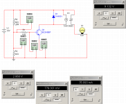
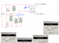
Using Multisim I managed to simulate the following that it works the way I want as when the LDR resistance changes to 35kohms the light bulb turns off. (Please note that in this new circuit I had to move the LDR to the top). I am also including the circuit showing how I plan to connect it to the PLC.
Please give me your thoughts about it. I am still wondering how this can be done using only solid state electronics. Thanks


Last edited:


