The Next Stage (1746-HSTP1)

Automater

Member
Join Date
Jul 2014
Location
SPain
Posts
47
Hello all,

Well I am back. I have been using and learning a lot about the SLC500 and I am able to use the Input / Out cards / Analog In / Out cards and I have done a lot. I have used the advanced HIM interface.

I would like to thank you all but now I have 1 battle where I need some help.

The 1746-HSTP1

Okay,

I have the following:

SLC500 Card - 1746-HSTP1
Stepper Motor - AXHM015K-30 (http://www.airlinehyd.com/APOLLO/ORIENTAL/AXH.PDF)
Driver - OEM750 http://www.parkermotion.com/manuals/OEM750/OEM750_Entire_Rev_B.pdf

So, I have the following, I saved up for a few months to buy this and now I need to set it up.

I understand that people can say, just go a learn. I have but, I feel that I need to approach this part with caution as I do not want to blow up anything.

Here are some of the objectives:

  1. Wire up the stepper motor to the driver
  2. Wire up the driver to the stepper card
  3. make a simple program to step the motor

Thank you all and I really need you help with this one.

Please note, I am not working for a company, I am doing this just to expand my mind.

Thank you
 
Update.

Okay, the stepper motor have 8 Wires.

In order, left to right (black, purple, blue, yellow, green, orange, pink, white)

If pass 6v through:

black and purple CW
black and blue CCW

The rest, nothing, am I missing something here?

3 Wire stepper motor?
 
The link you provided is to a DC motor and variable speed control - NOT a stepper motor.
The part numbers in that datasheet don't match exactly with the part number you provided and the color codes are not exact (you mention blue and pink - datasheet does not have those listed).

A stepper motor would normally be 4 or 6 wire.
If you applied some voltage to the correct pins of a stepper driver you would likely only get one step, not a CW or CCW rotation.


Well, that is fantastic.

Ok. thank you danatomega. I spent all night learning about the stepper controller and driver. Okay, so I need a stepper motor.

Does anyone have 1 that can sell me in Europe.

Could I use this?

http://www.ebay.co.uk/itm/BERGER-LA...48?pt=LH_DefaultDomain_77&hash=item3cf94a6b30

or

http://www.ebay.co.uk/itm/MINEBEA-A...561?pt=LH_DefaultDomain_3&hash=item2a46d69d71

I really appreciate the support.

Thanks
 
Okay. Great news. I have a Stepper motor connected to the Driver - OEM750. And all is working.

I just need a littler help connect the Driver - OEM750 to the AB 1746-HSTP1

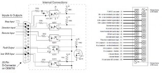
The image below show the connections for the OEM750 to the AB 1746-HSTP1

I guess I would have to supply 5v to connections 1 & 18 on the 1746-HSTP1?

Please let me know

THANK YOU!!!!! :)(y)(y)(y)(y)

OEM750 & HTSP - Copy.jpg
 
Last edited:
Both the manual and your included diagram say that pin-1 get 7-24 VDC. I don't think 5VDC is going to be sufficient.

If you're trying to match the 5VDC shown on the OEM750 diagram, it shows that all the external signals are opto-isolated so you shouldn't worry about matching the voltages.
 
Both the manual and your included diagram say that pin-1 get 7-24 VDC. I don't think 5VDC is going to be sufficient.

If you're trying to match the 5VDC shown on the OEM750 diagram, it shows that all the external signals are opto-isolated so you shouldn't worry about matching the voltages.

Thank You.. I have it working

GREAT... Now the next part!!!!!!!!!

I have to work out the coding required.

Thank you

Should I create a new POST?
 
I don't really know the rules for that, but I believe you can continue this one since it's all related to your original post...
 
Ok, I have an issue. I can get CW to work however CCW does not work.

This works, acceleration, and deceleration
Clock Wise
N7:10 128 - 0 - 0 - 0 - 50 - 0 - 50 - 40 - 0 - 0


This dose NOT work. The green LED does come on. So, I think it is about the wiring
Count Clock Wise
N7:10 256 - 0 - 0 - 0 - 50 - 0 - 2000 - 2000 - 0 - 0

The OEM750 & 1746-HSTP1 use the same power supply, AB PSU 24V

OEM750 - 1746-HSTP1

PIN 1 - PIN 2 (CW + or non directional pulse output)
PIN 2 - PIN 3 (CW - or non directional pulse output)
PIN 3 - PIN 4 (CCW + pulse or direction signal output)
PIN 4 - PIN 5 (CCW - pulse or direction signal output)

Please have a loot at the image below. I am not sure if I have missed something out.

Stepper Wiring.png
 
See page 1-4 of the HSTP manual:
http://literature.rockwellautomation.com/idc/groups/literature/documents/um/1746-um121_-en-p.pdf

you need to configure it for EITHER
pulse train with direction command -OR- a CW pulse train and CCW pulse train

I'm unsure how you have it configured.

Okay, that is great, I have been through the manual so many times. DO you know where / how it can be configured??? At this moment, everything is default, I assume.

THANK YOU A LOT!!!!!!!!
 
Last edited:
See page 1-4 of the HSTP manual:
http://literature.rockwellautomation.com/idc/groups/literature/documents/um/1746-um121_-en-p.pdf

you need to configure it for EITHER
pulse train with direction command -OR- a CW pulse train and CCW pulse train

I'm unsure how you have it configured.

Hello,

Okay, I have been through the OEM750 Manual. I have found this information.

STEP INPUT
For every step pulse it receives on its step input, the drive will
commutate the motor to increment rotor position. To send a
step pulse to the drive, apply a positive voltage to STEP+ with
respect to STEP–. The drive registers the pulse on the rising
edge.

The step input is optically isolated. Driving the step input
1differentially will provide the best noise immunity. Your input
driver must provide a minimum of 6.5 mA—approximately 3.5
VDC. With no external current limiting resistor, the current is
controlled by the applied voltage. This is due to a fixed voltage
drop of 1.7VDC on the opto LED and the internal series
resistor (243). Increased voltage will result in increased
current.

Step Pulse Requirements
Operate the step pulse input within the following guidelines:
• 200 nanosecond pulse – minimum
• 40% – 60% duty cycle (2 MHz maximum pulse rate)

DIRECTION INPUT SIGNAL SPECIFICATION
While a positive voltage is applied to DIR+ with respect to
DIR–, the drive will commutate the motor in the clockwise
(positive) direction as it receives step pulses on its step input.
While zero voltage (or a negative voltage) is applied to DIR+
with respect to DIR–, the drive will commutate the motor in
the counterclockwise (negative) direction as it receives step
pulses.
The input is optically isolated. It may be differentially driven.
CAUTION
Reverse voltage in excess of 6VDC may damage this device.
Your input driver must provide a minimum of 8mA at 3.5VDC
to ensure proper operation. With no external current limiting
resistor, the current is controlled by the applied voltage. This
is due to a fixed voltage drop of 1.5VDC on the opto LED and
the internal series resistor (243).
 
Apparently the stepper driver is not protected against reverse voltage, so you must use from -3.5 to -6 volts only.
CAUTION
Reverse voltage in excess of 6VDC may damage this device.
Your input driver must provide a minimum of 8mA at 3.5VDC
to ensure proper operation.
 
Last edited:
Apparently the stepper driver is not protected against reverse voltage, so you must use from -3.5 to -6 volts only.

Hello,

Okay, 7 - 24v must be supplied to the AB 1746-HSTP1.

So, am I missing something here.

I have supplied 24 to the 1746-HSTP1. Everything work in a CW direct however I cannot get the CCW working yet.

Thanks
 

Similar Topics

I've got this start screen where the user has to enter their username and password. The username and password feature works fine. However, I want...
Replies
7
Views
1,421
Anyone know what the little green triangle on SCREEN 3 means ? See picture Thanks
Replies
2
Views
447
What do you guys think of this representation for on/off contacts? C003 is on, then others are off. I have never seen the logic represented in...
Replies
5
Views
1,797
Is it possible to get a report about used digital inputs on GE Proficy? I want to set what inputs are available.
Replies
3
Views
1,075
Hello PLCS.net! Link here: https://www.rockwellautomation.com/en-us/products/software/factorytalk/whats-new.html Seems like Rockwell is actually...
Replies
33
Views
22,417
Back
Top Bottom