Flashing Output On and Off

Have you ever used the histogram or the timing in rslogix.
they represent realtime of anything in the prog that you wish to view.
It is a great troubleshooting tool, and if you haven't used them give them a try and become familiar with them. If you know about and have used them then great and this post is for everyone else that's following.

Drewcrew6
 
Drewcrew6 is correct - the histogram is a great feature ... but ... regrettably it is flawed in the SLC and MicroLogix processor families.

When you do a histogram with the larger PLC-5 (specifically the enhanced line) family of processors, the processor itself monitors the status of the histogram's bits. Then, whenever the processor gets a chance to communicate with your computer, the processor sends over a "chunk" of data to update the histogram charts. Incidentally, this "chance to communicate" does NOT come around on each and every scan. But even so, since the PLC-5 processor is keeping a close watch over the bit status internally, the PLC-5 histogram will give you pretty durn good results.

On the other hand, with the smaller SLC and MicroLogix processors, the processor itself does NOT monitor the status of the histogram's bits. All of the data on your screen MUST STILL come through the (relatively) slow serial cable. In other words, the bits may go off and on several times before the histogram (which lives ONLY on your computer) gets a chance to check their status. So with these systems the histogram will update its status in "fits and starts" and your flashing pattern (even though it might actually be perfect) will still look erratic.

So play with the histogram by all means. In many cases it may help you find the answer to a knotty troubleshooting question. Just be aware that (when using an SLC or MicroLogix) just as the screen lies - so does the histogram. I've seen technicians attempt to use this thing for days while troubleshooting a problem - only to find out later that the histogram had been lying to them all along. This is much like having intermittently broken leads on your volt meter. If you can't trust your test equipment - then whom can you trust?

And incidentally, for those of you who’ve never heard of it before – the histogram is found under the RSLogix500 menu at the top of the screen under “Comms”. Unfortunately you must be Online with a processor to even see it – it will be “grayed out” on the menu when you’re Offline.

Again - to monitor the action of the flashing pattern, send the flashing action to a real-world output to see what's really going on. You don't have to actually wire up a physical output of course. You can watch the action on the output's LED.

Now on to your "LEQ" solution to the ABSOLUTELY NO FLICKER problem. That’s great for the 100% end - but now what's going to happen when N7:0 is set to zero - for 0% flash?

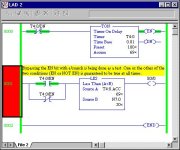
And on to the “shorted branch leg” error. You are right – I was wrong. You can’t download this “unconditional test branch” to a MicroLogix 1500. I’ve used this technique for years with PLC-5 and SLC-500 systems – now the old dog must learn a new trick. So since the “short it out to test it” concept is still valid – how about the arrangement below? This works fine because the Enable bit (in fact, any bit) can’t be off and on at the same time – so one of the paths is always guaranteed to be true. And I just went and got a MicroLogix 1500 off the shelf and tried it – it downloads and works fine.
[attachment]
Also another apology. When I told you to experiment with S:42 in an earlier post, I was thinking of the Real Time Clock Seconds word in an SLC – I had forgotten that you are using a MicroLogix 1500. I guess I’ve got to spend more time playing with the newer toys around here.

bypass.jpg
 
Ron Beaufort said:
Drewcrew6 is correct - the histogram is a great feature ... but ... regrettably it is flawed in the SLC and MicroLogix processor families.

Not only that it is not included in all versions of RSLogix.

Ron Beaufort said:


Now on to your "LEQ" solution to the ABSOLUTELY NO FLICKER problem. That’s great for the 100% end - but now what's going to happen when N7:0 is set to zero - for 0% flash?

You get one flash each time the timer is reset. So to solve that I did the following.

ladder8.jpg


May your Crayfish jump into your pot of boiling water...

Thanks
John
 
I was unaware of that fact Ron thanks for shedding that light.

But that brings a question to mind. Does the complete I/O table update on the computer every comm period, or just whats relevant to the screen?
I would think the whole table but if its just whats relavant it would seem that the histogram would run much cleaner with all windows closed(obviously except rslogix on-line and linx).Also would it run more effiecantly with linx not in autobrowse (never tried setting it that way while on-line)? Also the comms type could then affect this due to speed and also the proc. speed of computer.

My largest use for the histogram is to watch for something to happen when i can't be at the laptop. I haven't really used it in a time critical situation.

The only time I found it useless was trying to catch a bit that goes true at top of logic and goes false at end or vice-versa (something overwriting that particular bit). I assume this is due to the comms happening during housekeeping in between scans.


Thanks again
Drewcrew6
 
Ron Beaufort said:
Drewcrew6 is correct - the histogram is a great feature ... but ... regrettably it is flawed in the SLC and MicroLogix processor families.
When you do a histogram with the larger PLC-5 (specifically the enhanced line) family of processors, the processor itself monitors the status of the histogram's bits.
<< snip >>

On the other hand, with the smaller SLC and MicroLogix processors, the processor itself does NOT monitor the status of the histogram's bits.
So THAT explains it! Thank you. I thought I was missing events on the SLC histogram, but was used to the PLC-5 one, and didn't think it was so. It was.

I think (but don't know for sure) that one way to inprove throughput between the SLC and PC/histogram is to close every open window and program subrouting (right click on the tab at the bottom of the screen and select REMOVE). It seems that only what you are looking at is updated (I've openned data tables and saw really old data for a moment before the screen refreshed and the SLC sent the data).


And on to the “shorted branch leg” error. You are right – I was wrong. You can’t download this “unconditional test branch” to a MicroLogix 1500. I’ve used this technique for years with PLC-5 and SLC-500 systems – now the old dog must learn a new trick.

This is why, on every project, I program B3/0 as ALWAYS OFF, and B3/1 as ALWAYS ON (Zero is OFF, One is ON - get it? My memory needs all the help it can get).

I'll use -| |- B3/0 as a replacement for the AFI instruction that I miss from the PLC-5, and the -| |- B3/1 on the shortened branches. Since there's something on the branch, RSLogix doesn't complain, but since it always solves as TRUE, I get the functionality that I want.
 
I used to like the "always off" bit idea too - until the other day when a customer called in with a "mission impossible" troubleshooting problem. He had used B3/100 as "always off" by UNLATCHING it at the very top of his program. Then some knucklehead came along halfway through the program and made a typographical error. You guessed it - he turned the B3/100 bit ON with his ladder logic. (He meant to use B3/10 but apparently got caught up in the magic of the moment and typed an extra "0" while entering the address). Everything from that point on down through the ladder which was GUARANTEED to be OFF was suddenly giving all sorts of mischief. The customer had been scratching his head over this all day - but as soon as I suggested a "Find All" over the phone, he had the problem solved in a few seconds. He had just never even considered that his "always off" bit could be UN-UNLATCHED.

Based on that sobering experience, I think from now on (when forced to do without AFI and unconditional branches) I personally will use XIC and XIO in series for all of my "GUARANTEED OFF" conditions - and XIC and XIO in parallel for all of my "GUARANTEED ON" conditions.

On the question of how much stuff gets updated - I'm working on some experiments there. Preliminary results indicate SOME (but not much) improvement by shutting down unused windows. I think the answer is going to lie in the fact that the processor communicates with the computer in "packets" which, even if partially empty, still require a certain amount of "overhead" time. I'll let you know what I find out.

And John, now that you've got the flicker worked out - take a look at the LIM (limit) instruction. Be sure to pay particular attention to what happens when the Low Limit is greater than the High Limit.
 
The LIM is neat. I wonder why it is not availible on the 5/01 processor?

So when you set the low limit above the high limit you get a true when you are below, equal and above the limits. That's neat. Kinda like a not limit.

Based on that sobering experience, I think from now on (when forced to do without AFI and unconditional branches) I personally will use XIC and XIO in series for all of my "GUARANTEED OFF" conditions - and XIC and XIO in parallel for all of my "GUARANTEED ON" conditions.

This one's going in my rule book too. What is "AFI"?

Thanks

John
 
Just a quick note on a trick I use when writting programs...I always pick a 'spare'input address way up above my used i/o limit and label it "DUMMY". then if I need to 'short' or test a rung or lock out arung at any time I just insert 'Dummy'. Work great. And if you want to turn on the test area or what ever, just force on your ' Dummy' bit.
 
jthornton said:

What is "AFI"?


AFI=Always False Instruction. It's a PLC5 instruction. There's no chance that it will be on at all. I like it because unlike the "always off bit" you dont even have to remember an address. (God, I'm lazy! :) )
 
David_Emmerich said:
And if you want to turn on the test area or what ever, just force on your ' Dummy' bit.

Or use an XIO instead of an XIC.
I'm not trying to be picky, I just try to avoid hitting that "enable forces" command any more than I have to. The one thing that I dont like (in this situation, though it can be handy in other situations), is that you can have forces installed but not enabled. So if you didnt happen to notice that something else was forced on (but not enabled) and you come along and force on your "dummy" input, and then "enable forces" you could have just opened the door for more problems.
 
Your circuit looks fine to me. Some comments: having been involved with PLCs for 25-odd years, circuits such as this are fine when they are properly documented. Given the poor state of training these days, the PLC programmer must take special care to fully document the code such that a maintenance person can understand it.

My main guideline with PLC programming is make things as simple and straightforward as possible; therefore I would have probably used two timers.

Another point is that rarely do we run into memory restrictions with today's PLCs. However, you circuit saves a timer and that is good.

Nice "out of the box" solution!

Best of luck,

Jim Davis
 
The little devil on my left shoulder is saying: “Go ahead – let’s play hardball”. The little angel on my other shoulder is saying: “Don’t do it, Ron – you’ll scare the children”. Well, some of the beginners in the audience may have to sleep with the lights on tonight – but here goes anyway.

David_Emmerich made an interesting observation in post #24:
I always pick a 'spare'input address way up above my used i/o limit and label it "DUMMY". then if I need to 'short' or test a rung or lock out arung at any time I just insert 'Dummy'. Work great. And if you want to turn on the test area or what ever, just force on your ' Dummy' bit.
No offense David, but personally I’m going to stick with my “series” or “parallel” constructions for “always off” and “always on” test conditions (as mentioned in my post #22). Let me show you why and see if you agree.

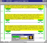
WARNING! The following program may be disturbing to young viewers. [attachment]
This is one of my many infamous “hardball” programs which I often use to demonstrate to beginners what REALLY goes on inside the PLC as it scans its program. It may not be a pretty picture – but it’s HIGHLY educational when followed all the way through its analysis. (You may interpret that as: “You ain’t seen nothin’ yet.”) So you see, even an UNWIRED input bit can be highjacked by a simple typographical error. (I actually stumbled across this phenomenon late one evening when one of my students accidentally typed in “I:011/5” instead of “O:011/5” as an address for an OTE). So based on all of this, I still like my old tried-and-true “series” and “parallel” test constructions. If THOSE ever fail, I’ll have to change careers.

And a quick note to our distinguished colleague 93lt1 (who, like myself) apparently has much more familiarity with the PLC-5 and SLC-500 platforms. We have to keep remembering that the guys in this thread are playing around with a MicroLogix-1500. The forces are ALWAYS enabled in this simpler processor. I got burned with my “unconditional” test branch (see posts #8 and #18) so I’m trying to be more careful now. It’s not easy moving into the “cheap seats” - but I’m trying to fit in.

Finally, an IMPORTANT note to all (and especially to Jim Davis – who seems to have a true appreciation for real-world programming techniques) – the material in THIS particular post is intended solely for educational purposes. I certainly do NOT recommend using these “Twilight Zone” procedures for real-world programs. I will, however, stick by my (well, actually by John’s) flasher solution of “one timer – and a LES (less-than) comparison” though. And yes, I’ll certainly agree that the GRT (greater-than) - which my incessant goading forced him to add - IS overkill. That too was purely for educational purposes.

And really finally, for those who are interested in the apparently “dirt simple” AFI from the PLC-5 instruction set, this is a direct quote from the RSLogix5 online help file:
This input instruction disables its rung when inserted in the condition side of the rung. Use for debugging programs and for temporarily deactivating a rung that will be needed later. Program an AFI as the first input in the rung. © 1997 Rockwell Software Inc.
I say that there are three (yes, I said “three”) errors in that short official description. This isn’t intended to knock the Rockwell Software developers, of course, but I think that our beginners need to know the facts. As jthornton said in another thread: "Inquiring minds want to know...."
but bit.jpg
 
Last edited:
Ron Beaufort said:
And a quick note to our distinguished colleague 93lt1 (who, like myself) apparently has much more familiarity with the PLC-5 and SLC-500 platforms. We have to keep remembering that the guys in this thread are playing around with a MicroLogix-1500. The forces are ALWAYS enabled in this simpler processor. I got burned with my “unconditional” test branch (see posts #8 and #18) so I’m trying to be more careful now. It’s not easy moving into the “cheap seats” - but I’m trying to fit in.


Ron-
I guess I should have read ALL of the above posts!
Thanks for clearing that up!
 

Similar Topics

Hello everyone, I am having issues with an output module connected to my 5069-L306ER PLC. The modules I have connected are a 5069-IA16 in slot 1...
Replies
1
Views
682
When trying to troubleshoot a machine at my factory, I was checking out the PLC and on one of the output cards there were a bunch of flashing...
Replies
4
Views
2,131
Hello there, Sorry I am quite new to this... thank you for taking the time to answer my thread. I have a small problem trying to get an output...
Replies
23
Views
5,085
Hi everyone, I have an output module that is blinking outputs 6 and 7 even when I take the wires out from the terminals. I thought it was the...
Replies
6
Views
4,920
Im trying to flash an output (50/50 duty cycle, .5 sec on/off.) I thought a TON/TOFF setup, but I cant get the logic down right. Is there an...
Replies
7
Views
18,290
Back
Top Bottom