Motor Control Education Questions

Hi Folks,
Thank you for all the feedback. We're planning on having an adjunct electrical engineer who does this stuff at work everyday to teach the course. If we had unlimited dollars and space - I would buy an amatrol motor control trainer but they cost around 50k a trainer. - This is the main reason I'm trying to build 4 double sided trainers. Im including the first 7 labs we're thinking about before we move onto VFDs, HMIs & PLCs. The first 7 labs will be what I would call - old school motor control.
Labs 1-7 here.......
https://www.dropbox.com/s/l8dpw3w7dlnkmad/combinepdf.pdf?dl=0

So from your feedback it seems....
1) Definitely need to remember that the line comes in at the top and the load comes in at the bottom.
2) We need to install a 3phase E-Stop on the side of the trainer.
3) Cover Forward & Reverse interlocking circuits
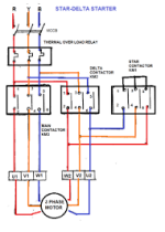
4) Wye Start - Delta Run motors stuff - This concept seems like it is for very large motors? Would this be called a Soft Starter in the states? I cant seem to find a Wye-Start Delta run motor starter in McMaster-Carr for some reason.

Anyway thanks for all the advice - this is an amazing forum with good people.
Tim
 
Last edited:
The term Wye is not often used in most countries it is Star/Delta try searching for that. VFD's are not Star/delta they perform a soft start operation anyway so depending on motor will either be wired in Star or in Delta. For a Star/Delta starter it requires 3 contactors, interlock, timer & overloads. Two contactors 1 for supplying 3 ph to 3 of the motor terminals and one that links out the other 3 terminals to start in Star, then after timer times out it de-energises the Star contactor & pulls in the other contactor that is also wired to these terminals. this puts it into Delta i.e. 3 phases on both sides of the motor.
 
3 Phase E-STOP

Im getting feedback that the trainer needs an E-STOP in a big way. Im thinking the proper location for an E-Stop is between the main disconnect and the inside terminals inside the enclosure. In order to do this - I would mount a 3 Phase E-STOP Pushbutton the side? I would come out of the main disconnect and then into the E-STOP? Why is it near impossible to find a E-STOP with 3 contacts for each phase? I think Im missing something...
Tim
 
Well... It depends on what category your e-stop needs to be for a simple motor starter that's not driving anything so not likely to cause injury then fit a safety relay that turns off the control voltage to the contactors. or if you want a safer way, do exactly the above but include a main contactor as well as the motor drive contactors and feed back to the safety relay the normally closed aux contact off the all the contactors If the e-stop is pressed, the safety relay drops out the control supply and the the main 3ph supply and the contactors, if one welds in the N/C contact on that contactor will be open stopping you from resetting the safety relay. look at the PILZ safety book there are plenty of examples.
 
To address your question about wye vs delta connections in the motor:

You DON’T have to worry about that. Whether the motor is INTERNALLY connected in wye or delta is of concern for the motor manufacturer only. When you (we) hook up motors in the field all we have to concern ourselves with is the proper connection pattern for the voltage we are connecting it to. So for example in your case, that motor is set up for dual voltage input; low or high. The low voltage rating (at 60Hz) is 208-230V, the high voltage rating is 460V. (In some circles this is referred to as “Tri-voltage rated because of its ability to accept 208V on the LV side). If it were used in a 50Hz country, it is rated for 190-230V low and 380V high, but that is superfluous information for anyone in the North America. In this case that motor is wound as wye for low voltage and wye-wye as the higher voltage. Did you need to know that to hook it up? No you did not, you only need to know the proper connection pattern.

So you picked the correct connection pattern for THAT motor. It might be different for another motor, you cannot generalize and be 100% sure, you MUST use the connection pattern given on the motor nameplate or diagram inside of the peckerhead. If there is no diagram because the motor is old, painted over, the plate rusted off etc., there are ways to determine what you have if you are desperate, but that is a more advanced set of skills that should not be part of a beginning course, they will RARELY have to use that (and if you don’t have the nameplate, you don’t know a lot of other important info anyway, so it’s something only done by desperate people). Teach to your audience; people taking beginning courses need to know beginning information, leave the tough stuff to the veterans.

The reason you see a number of YouTube videos on this issue is simply because a LOT of people get confused by this issue. That’s because they conflate the way the MOTOR is built INTERNALLY, to how the SUPPLY source is configured at the SERVICE ENTRANCE. They are NOT the same thing and are TOTALLY IRRELEVANT to each other. THAT is worth teaching to beginners. From the motor connection standpoint; all you care about is matching what voltage you have and what the motor needs. How it is delivered or connected with regard to wye vs delta is totally irrelevant to THIS issue.
 
Last edited:
Read the motor plate ! it could be 240v delta 415v Star or some other voltage (dependent on country) i.e. 415v delta 660 star so if your supply is 415 then direct online it will require the motor to be set in what it says on the plate. They usually come with jumpers set to either configuration so check first. You only need star/delta for large capacity motors or better still use soft starts or invertors.
 
True, an Estop may be necessary.

However, in a single motor controller, typically the stop button is a mushroom-type that latches and pulls to reset or twists to reset.
 
Not a wiring issue, but I'd add a load to the motor. It could be a fan from an old furnace or a hydraulic pump dumping over a relief valve. The purpose is to illustrate current variation with load. It should also be used to illustrate that the load determines the power draw, not the motor. It is a simple thing but causes a lot of confusion. I've seen graduate engineers make mistakes because of that concept.

I teach some classes at the University of Wisconsin, Madison on controls. If you send me a private message through the forum we can exchange emails and perhaps I can help further.
 
be careful with the E-Stop
and E-Stop requires a safety relay and a double safety contactor to need current code
you really need to enlist the services of an experienced controls engineer
if you are teaching new students you need to make sure they understand the meet the current codes other wise they will just get in trouble in the field
I have seen small panel shops build panels without the standard safety relays but if somebody gets hurt that will be held liable for it. Save a few cents now and pay big for damages later
 
Another thing if you are using 2 motor why not set one up as a load
couple the shafts together run one in regen mode the new drives are line regen it would be a good learning experience
it could also be used to show speed tracking ( Master - Slave)
 
Tom is correct!
You need a load. A homemade proney brake will work. The students can see in real time the current and rpm change. They can also watch the overload trip. They can also start a motor under load.
 
be careful with the E-Stop
and E-Stop requires a safety relay and a double safety contactor to need current code


This is news to me, would be interested in seeing it in writing. Do you mean meet code or to meet a certain level safety category?
 

Similar Topics

Kindly, has anyone tried to control Lenze servomotors with Siemens S120 drives ? Any special hints ? Have some concerns for the resolver and servo...
Replies
5
Views
218
Hey there, I just have a motor related question. I am using a 90V DC motor (https://www.motion.com/products/sku/03889770) and am controlling it...
Replies
1
Views
235
Does anyone have any experience with working on piezoelectric motor control? I want to use off the shelf components to hopefully change the...
Replies
5
Views
731
I'm controlling an Applied Motion HW23-601D using a Leadshine EM542S connected to a 2080-LC50-48QBB, using CCW, and experiencing some weird...
Replies
2
Views
599
This is my first time doing any sort of motor controls with PLCs so I am looking for some help determining what kind of equipment I will even...
Replies
8
Views
1,212
Back
Top Bottom