You are using an out of date browser. It may not display this or other websites correctly.
You should upgrade or use an alternative browser.
You should upgrade or use an alternative browser.
How to program an analog I/O Module?
- Thread starter azecraze
- Start date
Ron Beaufort
Lifetime Supporting Member
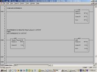
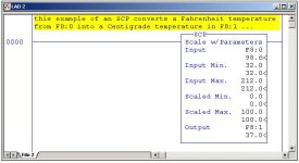
basically your first two rungs are “not normal” to be polite ...
we don’t usually set up an SCP using the same values for “input min/max” and for “scaled min/max” ... in other words, you have set up each SCP with a one-to-one relationship between its input and its output ...
specifically ...
your first rung will simply copy the value from I:2.0 into N7:10 ...
your second rung will simply copy the value from I:2.1 into N7:11 ...
two simple MOV (Move) rungs would accomplish the same thing ...
and since the inputs and the outputs are each composed of two CONSECUTIVE locations, a single COP (Copy) rung with a length of “2” would be even more elegant ...
sorry ... don’t have enough time to analyze the underlying logic ... hope this little bit helps ...
PS edit ... I deleted my first post ... I wrote it before you got your second one posted ...
Last edited:
Ron Beaufort
Lifetime Supporting Member
No problem, I stand corrected. It must be getting pretty late on your side of the world.
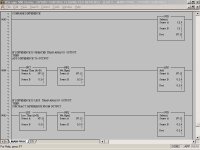
Here is a revised ladder, minus the SCP. The reason I had it in there, was because I didn't know where to bring the analog input to.
I guess I still can keep it in there if I wanted to scale it to engineering units, rather than leave it as raw data.
So according to Allen Nelson, the analog output should not change unless a difference is detected on the 2 inputs...El Perfecto!
Or is this too soon to be jumping for joy?
Comments Please.

Mtn_Bkng_Dave
Member
Ok what if.............
I see what you are trying to do but.........
Why not put a level indicator to monitor your impoundment level...Use this analog signal to control the needles on the turbine nozzles or whatever flow control device you have. This will optimize water usage by maintaining maximum head and matching output to water availability.
To load the element bank, monitor the power flow from the grid INTO your local system. Use O as a setpoint ( you may want to consider a slightly positive current from the grid to pad reaction to switched loads so that you don't trip your reverse current relays and scram the turbine.) And use a control loop to pad the element bank against this setpoint.......
I understand what you are trying to do but maximum head is more important to optimziation and maximum power than water flow as they are inversely proportional and will affect your calculations and algortithms.
Dave
azecraze,
Maybe I can help some, having some experience in both PLC programming and hydro generation. Something I noticed right away: what happens if your Current Output is ever larger than your Water Flow? Then the difference will never be larger than O:2.0!
You might need to take the absolute value (ABS command block) of the Difference between Water Flow and Current, then do your compare rung.
Last edited:
Lancie,
You just happen to be a few steps ahead of me.
This is the way I see it:
If the current flowing from the turbine is greater than the water flow, then the extra current will automatically be taken up by the mains, as the current flow out of the turbine will only be equal to the water supplying it. If the water increases to be greater than the current flowing from the turbine, then THAT DIFFERENCE is the one that needs the load dump.
So we should only be working on the positive side of the equation. Any thing less than this is no load dump.
Energy is allowed to flow from the mains, but not back into the mains.
Please explain what the ABS block actually does, because the instruction set help is very vague.
Mtn_Bkng_Dave :
What you are saying is exactly right except that I am confined to working with what I have.
I have a radio TX at the head works, with relay output RX at the turbine measuring four different levels.
This is a bit coarse to be called analog, and it only cost NZD1100 (USD700).
I am using a radio because it is rainforest country.
Everything else I think would work in with what you say.
Last edited:
Mtn_Bkng_Dave
Member
Analog
Course is better than nonexistent. Could you use the 4 points as a hihi, hi, lo, and lolo? If so you could, with some creative programming, use this to pulse control the turbine flow valve. Small changes to the injection flow position on the lo and hi setpoints. Larger changes based on Lo Lo and Hi Hi. Not quite as effective as anaolog but based on your impoundment area can still be a very workable solution for level control. Easily controllable to +/-.5 meters. Especially with the relative small amount of flow you are talking about.
My main concern for your application is that the water flow/power output ratio in a turbine is not a linear relationship to begin with and even more pronounced in an impulse style turbine. Add to this the inability to regulate head pressure via impoundment level and you have a very complex sliding ratio curve to deal with. In other words 20 cubic meters per second of water at 100 meters of head will develop twice as much power as 20 cubic meters per second at 50 meters of head, by rule of thumb. However, add to this efficiency curves of the turbine, nozzle attack angle etc and its not even close.
Just out of curiosity why not sell the excess power back to the utility? Thank goodness here in the United States they have to buy it from you if its a clean renewable energy source. The only catch is that it doesn't say what they have to pay for it.
Dave
This is the third try to post this, hope it gets thru.
Thanks Mtn_Mkng_Dave. You have brought up some valid points.
Firstly the level switches on the impoundment are working exactly the way you have described them. eg LOLO LO HI HIHI on the governor, but the governor is absolute trash and no decent control possible. Hence the electronic load dump.
Second the sliding curve ratio of the waterflow/power output.
Well.....umm....you kind of have me there. Hows this for a lark:
Maybe I can just manually find the correct ratio for a given state and fix it there. Once I have some fixed points then I should be able to have scaled steps so that each step is scaled for the range it is supposed to control. In each step it would be ineffecient in the lower end and more efficient in the upper end or vice versa. but the overall efficiency would increase dramatically.
Now back to PLC programming, which I notice is coming under scrutiny....
Does the ladder I posted on POST #20 seem to be heading in the right direction? eg:
Compare 2 analog inputs, and add or subtract the difference to/from the analog output if any difference is detected.
Mtn_Bkng_Dave
Member
Yeah it will work........
Just in a round about way........
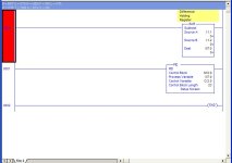
Why not use the output as the result in the sub statement and lose the last two rungs.
On the subject of speed control.........how do you plan to monitor the frequency to regulate the load bank when you run stand alone? Do you have a frequency output or anything?
As for the governor what kind is it? Is it a flyball or a more sophisticated digital?
Dave
The reason I cant just use the output on the sub is because that when it computes the difference, then the load bank increases the load on the turbine thereby reducing the difference to zero. This effectively
shuts the load bank off again. Creating a seesaw effect. So I need to "latch" the output so it maintains the analog output until the difference deviates from zero again. Does this make sense? This was mentioned in one of my earlier posts.
Standalone: The same load bank is used on stand alone to control the speed, using a separate controller. The analog control is switched between the two. The other controller is fed by a Frequency to Pulse Convertor custom designed by AB NewZealand. Its a pretty simple thing that sinks 24v every cycle.
The governor is an old 24v motorised worm drive thing. Really sluggish and cumbersome. This is not a brand new plant, it's a transfer and upgrade. In fact I think that by the time we are through, the governor will be the only original thing on it!
The actual control of the governor is done by the PLC.
Mtn_Bkng_Dave
Member
Mtn_Bkng_Dave
Member
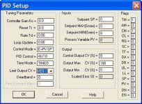
Setup like this
Your setpoint will be 0 and any difference will cause the output to modulate accordingly. It will take some tuning to get it right but it should be capable of tracking the load. I didnt put any PID parameters in cause ya gotta tune it.....I have no idea how responsive it will be to change so you will have to tune it after its put online.....It however will be as responsive as the modulation you are using to vary the load on the load bank. This being the cause I predict a very low proportional band. Also integral and derivitive will probably be as low as possible. .1 and .01 respectively. You need to decide to process STI or TIMED based on the scan time of the program and how fast the load bank responds to output changes.
Dave

Last edited:
Mtn_Bkng_Dave
Member
Now back to the governor
Yeah the old school stuff really stinks.....Toss the governor in the river........Would be really sweet if you could get that frequency pulse into the PLC and you could really do some trick stuff on it.
I just replaced a 1919 model governor on a hydrostation up the river from mine at the water system here......All high pressure hydraulics instead of the old slow lowpressure stuff. Didn't want to fool with rebuilding the old low pressure cylinders AGAIN. Tossed yet another set of flyball governors in the scrap heap.....Kinda funny tho...they had the first variable speed drive for AC motors......whether they wanted em or not! Hehehehehe
They never run stand alone so we just crank the power...They are always synched to the grid or the standby generator...
They just crank them to the point where they are about to sell some power then they dial them back......If you dont sell.......no FERC to deal with......
Dave
Similar Topics
Hello, the PLC in question is 1769-L30ER. I have a local 4-20mA Analog Output module (1769-OF4CI), and also a remote ethernet PointIO analog...
- Replies
- 0
- Views
- 394
Curious, is it common to program in offsets to calibrate/correct analog sensor readings in certain applications? As an example, I have a couple...
- Replies
- 11
- Views
- 3,058
Hi Guys,
How is Analog 4-20mA Level sensor Programmed in CLICK software of Automation Direct?
Which Instruction set.
- Replies
- 5
- Views
- 2,208
this is my first time using the analog programming . i want to take the input from the thermocouple and display it, I'm using step7 and plc...
- Replies
- 0
- Views
- 1,118
Help with a program setup. I am using a micrologix 1400 and inputting a 0-10VDC analog signal. My application is a part width measurement. The...
- Replies
- 3
- Views
- 1,871


