PLC/HMI What is the norm? Analog scaling.

bogu

Lifetime Supporting Member
Join Date
Mar 2020
Location
Alberta
Posts
22
I’m trying to perfect the HMI interface for analog configuration. I’ve provided the user the same options for all analog inputs, as follows.
  • Lower Calibration Value = 4mA
  • Upper Calibration Value = 20mA
So what is the normal approach when the signal drops to 3.8mA, and the scaled result becomes negative?
  • On the PLC, force the value to 0? For me it’s nice to see the negative value, for troubleshooting, but it messes up the alarm settings.
  • I’ve thought about using the 0-20mA? (and losing a few bits of resolution).
I’m trying to keep the interface generic but hopefully still useable - to expedite deployment by developing a generic template.
Best regards,
 
Leave it without clamps or you will not know if it is out of calibration/ under range/ over range, also depending on the PLC, you may need raw min/max as some do not have auto scaling built into the card, so perhaps IN Min In Max, Out Min, Out Max plus a good thing is if you can change the colour of the border or the scaled value when outside the limits.
 
What is the bit resolution of the input?


If it's 12 bit (so 4096 bits) make anything below 48 under range and anything above 4048 above range. Then you have 4000 point of resolution...
 
Short answer, it depends on a lot.

In some situations you'd want to throw the value to the highest range in other situations you'd want it thrown to the lowest range. Mostly for the operator and to create another layer in the software to catch all expected behaviour of a really bad condition.
 
Yep, as well as have limits on the values that can be entered (perhaps type of conversion i.e. 12 bit 14 15 etc.) checks so that the lower cannot be higher than the higher etc. so could get complicated.
 
Some transmitters have a nominal operating range for the output signal of 4-20mA, but will work fine below and above these limits when the measured value drops below or above the corresponding measuring limits.
So it will probably just generate a lot of false alarms if these are triggered at 3.99 mA and 20.01 mA.
We have a programmable limit depending on the sensor. Typically below 2.5 mA and above 21.5 mA will trigger the alarm.

Do not 'clamp' the scaled engineering value, not even when the alarm is triggered. That is a big no-no.
The PLC program must take the situation into account when a sensor goes bad. Each case is different.
 
* Do not clamp, unless you are using unsigned data types.
I had a "funny" moment when during the start up of a control system upgrade (all variables were uint) where the operators said: "Strange, the values seems to jump between 0 and [maximum] value". 🙃
 
* Do not clamp, unless you are using unsigned data types.
I had a "funny" moment when during the start up of a control system upgrade (all variables were uint) where the operators said: "Strange, the values seems to jump between 0 and [maximum] value". 🙃
If you are using unsigned data types for analog process values, the stop right there and change them to signed data types.
Counters that can only move in one direction can be unsigned, but even then why using unsigned just to save one bit of the value ?
If your integer count can ever get near rolling over, then it should be double integer, and if the double integer can get near rolling over it should be a long integer, and if the long integer can get near rolling over then what the h**k are you counting ?
 
@JesperMP


Well this was an upgrade of an old SattCon control system and the client didn't want to make changes in the SCADA (Ifix) so everything had to remain as UINT.
 
So it will probably just generate a lot of false alarms if these are triggered at 3.99 mA and 20.01 mA.

If any of you guys ever use Rockwell's 1719 IO (which is rebranded Pepperl-Fuchs LB IO system), don't trust the analog input card diagnostic for this precise reason. The fault bit is activated with these exact conditions which turned out to be a massive headache on an automatically generated PLC program. We had 200 analog inputs on that system... not bad, but it took a fair bit of time to get through it.
 
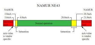
NE43 Analog Standards

Here is a good article explaining a standard that many manufacturers follow.

https://instrulearning.com/general/namur-ne43-standardization-of-4-20ma-signal-levels/

Of course there are always outliers as
we have 0 - 20 ma pressure transmitters that
4 ma = 0 psi
3 ma = - 20 psi

Our UDT's have place holders for 20 options per analog device
You chose to use some or none

Low Hardware Fault = Broken Wire
Under range = Transmitter Alarm
Low Low = Process Action Alarm
Low = Process Warning Only
High = Process Warning Only
High High = Process Action Alarm
Over range = Transmitter Alarm
High Hardware Fault = Miss Wired or Shorted

Then 12 User defined optional alarms

Namur.jpg
 

Similar Topics

I’m trying to perfect the HMI interface for alarm control. I’ve provided the user alarm options for all analog inputs, as follows. HH Boolean...
Replies
4
Views
1,471
Hi, Wy we log data in PLC using DLG instruction, when we have option to log data in HMI
Replies
1
Views
63
Hi, I'm thinking about using commands for Melservo J5 controller via HMI without PLC. Have you guys done this kind of control configuration for...
Replies
3
Views
139
Hello, I have an automation direct d2 262 plc and C-more HMI EA9T6CL-R. I need to prepare a program, scheduled to be performed on a future date. I...
Replies
1
Views
114
Hi Iam using monitouch hmi(V9 soft) with omron plc cj2m (CX programmer). In this I want to read a data from hmi to plc. The data was like...
Replies
0
Views
90
Back
Top Bottom