Mitsubishi Q series: how can I detect current in a power cable...

Mas01

Member
Join Date
Oct 2020
Location
Leicester, England
Posts
1,105
I need to send a signal to our PLC (Mitsubishi Q series) which is TRUE when there's current flowing and FALSE otherwise. The thing is, the cable in question is high current and I am trying to avoid any electrical changes since a contractor installed the electrical control panel and circuitry. I don't want to invalidate any warranty or something like that, and there's some huge earthbars in there that scare me.
Is there a non-intrusive way to detect current flow which I can route back to the PLC. All I need is a lamp on the PLC screen to indicate power is on.
This is needed on the PLC because sometimes the circuit breaker (see picture) trips to the OFF position when we don't expect it to. Thanks
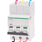
IMG_20220721_150809.jpg
 
Last edited:
The typical way is to use a current transformer (CT) on each phase, they typically give analog feedback, but you could either program it so that if that analog input > 0, then turn on a light. There also might be options for CTs that have digital outputs.

Google "donut current transformer" to see what they look like.
Cracking solution! I didn't even know such devices existed. This looks ideal. Cheers
 
Cracking solution! I didn't even know such devices existed. This looks ideal. Cheers

Glad to hear that they might be an ideal solution! I would actually recommend a number above 0 (maybe 5% of the expected range) if you end up going the analog route, as noise on the analog signal may trigger false positives on the current detection.
 
Glad to hear that they might be an ideal solution! I would actually recommend a number above 0 (maybe 5% of the expected range) if you end up going the analog route, as noise on the analog signal may trigger false positives on the current detection.

Thanks for the recommendation. Not for the first time you've helped me out. Cheers
 
The circuit breaker is rated for 40A, so this might do it.
https://uk.rs-online.com/web/p/current-transformers/9145284

That looks like it would do the trick, the only thing I can think of with that style is they require you to unwire each phase from the circuit breaker to pass the conductor through the hole in the transducer. There are CTs that actually open on a hinge so you can leave the power conductor connected to the breaker. I don't think the style you posted should be an issue, because one would hope that the panel would be powered down anyways, and disconnecting the conductor shouldn't be a problem in that case.

EDIT: I'm also looking at Automation Direct and they do have current switches as well, so something like that would give you a clear on/off indication.

Yes, I noticed that too about the closed loop (pardon the pun)...I'd have to pass the cable through the hole (does it matter which one? Obviously one of the three on the side that carries no current when the CB has tripped.
We might go for the hinged version, we'll see. Thanks
 
There are things you need to be aware of.
1. A current transformer to 4-20 & the Analogue card my not be fast enough to detect some short spike i.e. overload, perhaps the breaker is weakening you will only know when it trips not what caused it.
A lot of expense to monitor a tripping breaker, I suggest you check the current with a meter (probably a clamp type) it may be that it is close to the tripping point check the expected current drawn when what ever it is feeding if too close to 40 A then also check type of breaker i.e. B C or D these have different instantaneous current trip for example a B type will trip between 3 & 5 times the current rated capacity motors often use Type B or C this is to allow the inrush current on start up.
Thanks for this.
Just extra info: The CB in question is pretty new, maybe installed a year ago. The electrical panel is used for supplying power to the cooling tower fans. There's 2 ways of controlling the fans. Either from the electrical panel or from the PLC (there's a keyed switch on the panel to select either local (panel) or remote (PLC) control). Even when the CB has tripped, you can attempt to start the fans & all the indicator lamps on the panel would suggest the fans are running even though they're not! It's difficult to know when this happens because all the lights indicate fans are on (but they weren't)... someone went on the roof once to check and said the fans are not on. Then we worked out it was the CB that had tripped. So now we want to show the CB status on the PLC screen so we know when the CB has tripped. Hope that all makes sense.
 
Last edited:
The typical way is to use a current transformer (CT) on each phase, they typically give analog feedback, but you could either program it so that if that analog input > 0, then turn on a light. There also might be options for CTs that have digital outputs.

Google "donut current transformer" to see what they look like.


It is 3-phase fan. All phases should have same current so only one CT is enought.
If only tripping alarm is needed then relay on one phase after circuit breaker or different circuit breaker with auxiary signal contact is enought.


Glad to hear that they might be an ideal solution! I would actually recommend a number above 0 (maybe 5% of the expected range) if you end up going the analog route, as noise on the analog signal may trigger false positives on the current detection.

o_O 40amps and 4-20mA to plc. Noise should not be problem at all if fan running is compared to couple amps and not to equal 0 amps.
 
o_O 40amps and 4-20mA to plc. Noise should not be problem at all if fan running is compared to couple amps and not to equal 0 amps.

Yes, I'm just thinking of raw data counts, i.e. 0-32767 or something like that. Noise could make it go above 0 in raw counts, so something like 200 should cut off that low end noise if it were to occur.
 
It is 3-phase fan. All phases should have same current so only one CT is enought.
If only tripping alarm is needed then relay on one phase after circuit breaker or different circuit breaker with auxiary signal contact is enought.


o_O 40amps and 4-20mA to plc. Noise should not be problem at all if fan running is compared to couple amps and not to equal 0 amps.

Thanks @Lare.
 

Similar Topics

In this sample programming, what does U4 mean? Any assistance would be greatly appreciated.
Replies
8
Views
234
Hi, I have a project with a R04CPU, RD77GF16 and a RJ71PN92 modules. The cell is given to me to change the program since the previous integrator...
Replies
9
Views
269
Hi One of the PLC's that I maintain/update is a Mitsubishi Q-Series, probably installed about 10 years ago. At the moment, ALL the wires from...
Replies
13
Views
1,161
Hello All, I have an existing Mitsubishi L06CPU-06 PLC, and I am going to add a new serial communication card, LJ71C24, for modbus communication...
Replies
0
Views
469
I’ve not had a great deal of experience with CC link (TP) so looking for some ideas. I have several iQ-R PLC’s most of them are on an Ethernet...
Replies
4
Views
1,384
Back
Top Bottom