Mitsubishi Q series: how can I detect current in a power cable...

Would it not be easier to install an auxiliary contact on the breaker and if its tripped send the signal to the PLC?

I don't want to invalidate any warranty or something like that,

I dont see a difference from installing an aux or power detection device... and I would push back on the manufacture for not having one anyway, this should be standard to any cabinet
 
Yes, I'm just thinking of raw data counts, i.e. 0-32767 or something like that. Noise could make it go above 0 in raw counts, so something like 200 should cut off that low end noise if it were to occur.


That is true. Rarely seen over 100 or 200 raw error counts for 4 milliamps. Noise is usually seen only on 4mA and not on larger milliamp values even if milliamps are simulated from field. Probably raw jitter comes from near cables and 0V cable differs.
 
Would it not be easier to install an auxiliary contact on the breaker and if its tripped send the signal to the PLC?


I dont see a difference from installing an aux or power detection device... and I would push back on the manufacture for not having one anyway, this should be standard to any cabinet

+1000

CT and analogue, whilst it will work, will be much more expensive.

The cheapest is an aux contact for the MCB, of failing that, an interposing relay with coil at 230V (one of the three phases - it's a 3 phase MCB so if you lose one live the link bar will ensure all 3 are broken...) and the contact at your PLC voltage (likely 24V DC).

If there is a motor overload after the MCB, I wouldn't be surprised if it had aux contacts already.

Also, if you are concerned about warranty issues on new kit, you should be pushing this back on the OEM to rectify this themselves; both on the basis of excess trips (MCB not rated properly etc), and poor design (MCB trip should signal PLC/cabinet lamp/HMI).

Lastly, if you do go CT route, yes we have AD supplier in UK, it is LaMonde Automation.
 
Last edited:
I'm not sure the motor overload aux would be useful as it wont necessarily indicate tripped if the MCB is going before the thermal overload, plus it sounds like there are multiple fans.

The auxillary contact on the MCB is certainly the cheapest and easiest to add; don't even need to break into any mains wiring.

Alternatively, if that part of the installation is still under warranty or whatever and your fan panel is not, then adding a 3 phase monitoring relay in that panel is another option. We have one of these in all our main and sub boards as a permissive for starting anything.

Fan operation proving is another issue of course, you could still have supply through to the fan starters but have a fan that isn't running for some reason (local isolator off, fan blades fell off, whatever). That's where a current switch or 4-20mA for current per motor is a good idea, for proving it is running correctly.
 
A breaker with an auxilary contact for opened/closed could be wired directly to the PLC if your concern is solely the state of the breaker. A current transformer will tell you a draw of 0 Amps when breaker is tripped OR if fans turned off.
 
I agree with some of the others regarding adding an aux contact & monitor that for a trip status. If you really need to add the CT for diagnostic purposes the only way it will work to gather some data is as follows:
Create a trend graph, add the analogue value, also add the start signal or running signal etc. then you can see the start/run command will be true while running so for example if the run signal is on but the amps fall to 0 after a time then it must be tripping after a run time no when first starting, if however, the run signal goes from stop to run & it trips somewhere close to that then there is a possibility that starting current is too high for the breaker, another diagnostic is if the trip happens when the current drawn is high then possibly the fan is being overloaded (not that fans are generally thinking more about pumps dead ending etc.
At least this would give information what might be causing the trip.
 
Glad to hear that they might be an ideal solution! I would actually recommend a number above 0 (maybe 5% of the expected range) if you end up going the analog route, as noise on the analog signal may trigger false positives on the current detection.
UPDATE: I went for a "ring" current transducer, in the end. With no current flowing in the cable, PLC reads in the range -1..+2 (digital value). With current flowing, value at fan startup was ~3000, which settles at ~2500 (equates to about 14mA).


Solution implemented, all seems to be working.
 
I need to send a signal to our PLC (Mitsubishi Q series) which is TRUE when there's current flowing and FALSE otherwise. The thing is, the cable in question is high current and I am trying to avoid any electrical changes since a contractor installed the electrical control panel and circuitry. I don't want to invalidate any warranty or something like that, and there's some huge earthbars in there that scare me.
Is there a non-intrusive way to detect current flow which I can route back to the PLC. All I need is a lamp on the PLC screen to indicate power is on.
This is needed on the PLC because sometimes the circuit breaker (see picture) trips to the OFF position when we don't expect it to. Thanks


You don't really need to measure current to determine whether a circuit breaker is tripped. It would be cheaper and easier to check for the presence of voltage. For that, a simple relay switching a discrete PLC input would suffice. If you want to verify 3 phase voltage, you could use two relays (one connected to Phase A&B and one connected to Phase B&C) and series the PLC input through the NO contacts in both relays.
 
You don't really need to measure current to determine whether a circuit breaker is tripped. It would be cheaper and easier to check for the presence of voltage. For that, a simple relay switching a discrete PLC input would suffice. If you want to verify 3 phase voltage, you could use two relays (one connected to Phase A&B and one connected to Phase B&C) and series the PLC input through the NO contacts in both relays.
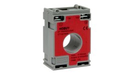
Thanks for this. I don't fully understand what you're saying as my knowledge is not good, but I went for a loop-style current transducer and passed one of the 3 phases through it. It sends 4-20mA and it seems to work fine.

R9145310-01.jpeg
 
Last edited:
Thanks for this. I don't fully understand what you're saying as my knowledge is not good, but I went for a loop-style current transducer and passed it through one of the 3 phases. It sends 4-20mA and it seems to work fine.


Sure. That will work.

It's just kind of like driving a thumbtack with a sledge hammer.
 
A current transducer will work, but might be overkill and will need an analog input.


To monitor a bank of industrial 24V 3-phase vibrators I added a current trip switch to one of the motor leads on each one.


I used these from NK, as I use their current transducers almost exclusively. Just wire it to a discrete input.


Also, a 377V coil relay wired from A to Ground (for 480V power) would let you know the power was on too.
 
Last edited:
CT was a good solution for this scenario. It's non-intrusive so shouldn't void any warranty.


It may be easier/cheaper to use an auxilliary or a relay to provide feedback, but that's either going to void said warranty or result in a conversion with the supplier who will point out that it wasn't in the original specification and it will cost £xxx to make the changes. By the time they've added their time, travel and updates to drawings the CT will be the cheaper option.


That said, surely a motor of that size is fed by either a VFD or a soft starter, is it possible to pick up a signal from there?
 
I don't think voiding a warrantee is worrying the OP, if you read the posts going back, there has been many changes, analogue control of tanks, level sensors, extra I/O cards, so a simple clipon aux is not going to make any difference.
 
I don't think voiding a warrantee is worrying the OP, if you read the posts going back, there has been many changes, analogue control of tanks, level sensors, extra I/O cards, so a simple clipon aux is not going to make any difference.


If anyone says 'Warranty Voided" they are going to have to prove how adding one sensor effected their machine.


If any addition voided a warranty then all the automobile manufacturers would be saving billions saying the fog lights, custom wheels, trailer hitch, roof rack, window tint, new radio, etc. might have effected the car and caused the engine failure.
 

Similar Topics

In this sample programming, what does U4 mean? Any assistance would be greatly appreciated.
Replies
8
Views
218
Hi, I have a project with a R04CPU, RD77GF16 and a RJ71PN92 modules. The cell is given to me to change the program since the previous integrator...
Replies
4
Views
142
Hi One of the PLC's that I maintain/update is a Mitsubishi Q-Series, probably installed about 10 years ago. At the moment, ALL the wires from...
Replies
13
Views
1,156
Hello All, I have an existing Mitsubishi L06CPU-06 PLC, and I am going to add a new serial communication card, LJ71C24, for modbus communication...
Replies
0
Views
468
I’ve not had a great deal of experience with CC link (TP) so looking for some ideas. I have several iQ-R PLC’s most of them are on an Ethernet...
Replies
4
Views
1,382
Back
Top Bottom