For the PID challenged.

Hi All-

I think I like it.
I don't do many heat or fill applications so I don't know how often I would be able to use this. But I definitely like the simplicity and the inherent predictive nature of it.
There, I used the 'P' word. I may be off the boat on this but the implementation looks to me like a type of model-predictive control to me.

I'll definitely keep this one in the tool box.

Keith
 
Greetings, Peter,

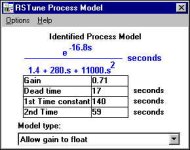
one more post before I take off for the weekend ... basically the graphs that I've been posting are just intended to give you the best possible idea of the Hotrod system's characteristics ... I know that you've got your work cut out for you in trying to write a program for a process that you've never even seen ... I'm trying to give you as much "up front" information as possible ... along those same lines, I ran the Hotrod through RSTune earlier today using the same settings and conditions as in my post #10 ... this is one of the things that popped up ... not sure whether it will help you out or not but here it is for what it’s worth ... have a good weekend ...

peter model.jpg
 
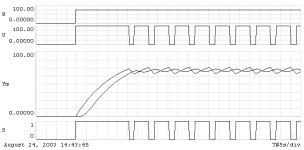
I got it SMC working on a SLC5/04

What really was handy was the trend.
SMC.bmp


One can see how the SMC does an excellent job controlling the actual temperature even though it is using the measured temperature to determine when the heater is turned on or off. Notice also that the actual temperature does not need to reach a steady state to accurately determine when the heater should be turned on or off.

I used the data from one of Ron's recent posts. Here he list two time constants. Time constant one for the heat source and sink. Time constant two is the sensor time constant. However, it was not clear to me what the units of gain were for the system. In a much earlier post he list a gain of 3.69 degrees/% output. In this case the maximum temperature I can reach is 3.69 * 100 or 369. I verified this by setting the SP to 380. One can see on the left side of the trend that the heater got to only about 369. If I waited long enough it may have reached 369 degrees.

I will post this on my FTP site tomorrow. I am going to clean things up and comment the program.

Ron, I still take issue with the dead time value that RS Tune calculates. Your heater should not have a dead time unless there is non-linearities or the material is moving to get to the sensor.
 
old stuff

Moin all,

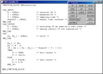
have done some simulations and "programmed" the SMC in ST.

There is nothing new in a Sliding Mode Controller. Non-linear control is old, old stuff. Get any book about non-linear control and don't bother if it is 15 years, 20 years old or more. You will find the mathematical background und many other control strategies using non-linear elements.

Friedrich Haase

smc_st.jpg
 
RSLogix 500 Version

Sliding Mode Control using a SLC5/04

I am having difficulties getting the link to work.
Goto http://www.deltacompsys.com/out/smc slc.rss

This example has a simulator that I used to test the code and a filter on the error rate. It also uses the trend which is a neat feature. However, I wish I could have done this in structured text like Friedrich.

Friedrich, nice example. SMC is old stuff but it is new to many here. There are few examples on the WEB and most text books do not give the subject coverage.

Ron Beaufort, try this out in simulator mode first. Then you will need to convert the on-off control to 4ma, 20ma control. You will also need the scale the analog input and put the floating point value in F8:1.
 
Last edited:
SMC - RSLogix 500 Version

Moin Peter,
moin all,

I am having difficulties getting the link to work.
Goto http://www.deltacompsys.com/out/smc slc.rss

Maybe the blank in the filename (%20) is not a good idea.

This example ...
However, I wish I could have done this in structured text like Friedrich.

You can
http://groups.yahoo.com/group/OATs1131
This is a news group, soon on a normal Web page.

Friedrich Haase
 
Control.com

There is a very interesting thread on the control.com board. Too Bad!

I also tried to respond and found that none of my post ever show up on control.com... This forum seem very helpful and friendly. I'll probably never visit control.com again.

I am interested in this type of control. Also, I am very interested in systematic approaches to feed forward model development and advanced control techniques.
 
Last edited:
The code is ready and sitting on my FTP site

I find it strange that no one has even tried the .RSS file or even made a comment. Almost half the program is the temperature simulator with which I tested the SMC code.

Can't anyone see that one can simulate a heater system? You can use the simulator part with a PID and practice tuning PIDs too.

I too am waiting for the results. Ron Beaufort may need to change the sensor time constant a little but the posted code should control pretty well. I have spent a few hours playing with the code. I made a version where the SMC time constant could be different from the sensor time time constant. This would happen if the estimate of the sensor time constant was off. I found I could be off by about a factor of five and the SMC would still control adequately. How is that for robust?

I also found that I could change the system gain. This is the 3.69 degress/% output. I found I could change this gain significantly with no ill affects. I could change the gain from 2.5 to 5 degrees/% output. Obviously there is a problem when trying set the SP too high. At 3.69 degrees/% will only allow the system to heat up to about 369 degrees. At 2.5 degrees/% will only allow the system to heat up to about 250 degrees.

Now here is the million dollar question. How does on find out what the value of the sensor time constant is? I know what Ron's is because he told me and he used RStune to get it.
 
I would love to see it, but I don't have any Allen Bradley software loaded at the moment so I can't open it and look at it. I would love to see the ladder if someone would be so kind as to post it I would like to port it over to AD and see how it works.
 
greetings to all,

sorry for the delay but i DID mention earlier that there would be NO time available this week (Aug 25-29) to get anything done on this project ... i'm hoping to have some extra time this weekend to get back on track ... i'll let you know the results as soon as possible ... i appreciate your patience ...
 
... first test results ...

Greetings Peter and all,

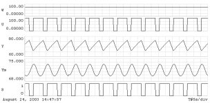
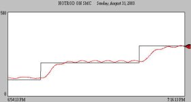
Sorry this took so long but every once in awhile the boss expects me to do some actual work around here. Last week was one of those times. Anyway here are the results of the first run of your Sliding Mode Control program when I ran it through the Hotrod. Throughout the entire test, the air flow (the load on the system) was kept at a constant 20% ... I started with a temperature setpoint of 100 degF ... and then increased it in steps to show the system’s response ... first to 200 degF ... and then to 300 degF.

[attachment]

As you can see, there is still some work to be done here. I’m going to go ahead and assume that I’ve left some “adjustment” stone unturned on my end. I’ll attach the actual program version that I ran in the next post so that you can take a look at it.

smc_a.jpg
 
... and the program version ...

This is the actual version of your program that I ran. I took the liberty of renaming it so that I can keep this and any subsequent versions straight.

[attachment]

Basically I had to make some minor changes to the I/O configuration table in order to match the hardware that I had on hand. I also added the SCP rung (as your rung comment directed) to scale the actual analog input (I:7.0) into your existing “PV_MEASURED” location at F8:1. One thing that you’ll definitely want to look at: Your original “simulated” signal ranged from 0 to 400 degF ... and my Hotrod thermocouple transmitter ranges from 0 to 500 degF ... is that an issue? You mentioned in an earlier post that I might have to “... change the sensor time constant a little ...”. I’ll be happy to do that ... could you suggest a range of values that you want me to try ... or possibly some type of “test” to more accurately judge the value that we need?

Let me know what you want to try next. Unfortunately I’m going to be very short on extra time this week also. Technically I’m going to be on “vacation” until Tuesday, September 9 ... but actually I’ll be “working” on my new garage/workshop in the backyard. Since I don’t do “internet” at home, it will probably be a couple of days after you post anything before I’ll get a chance to see it and respond. Thank you in advance for your patience.

PS edit to icky812: I tried to convert this to a .PDF file for you ... but it wouldn't work ... maybe someone else will get it done before I have a chance to try again ... sorry ...
 
Last edited:
Not too bad, at least it would burn the place down.

Things to try:

1. make the update interval shorter. Try .5 seconds
2. make the sensor time constant longer. Try 70 seconds.

I look at the code this evening.
I have got to get some sunshine while it lasts.

I made a mistake in the simulator that I will fix. I didn't take into account ambient temperature in the SLC version. My simulator will decay the temperature to 0 which we all know is not right. The temperature should decay to ambient or about 70 degrees F. This means with the gain you provided origignally of 3.69 degrees/% this would allow the temperature to go to 3.69 * 100 + 70 or 439 degrees.
This means the your graphs should be scaled to 500 degrees.


For the AD users.

SMC on a Automation Direct DL250.

Note, I don't have intialization routines in this version so the coefficients must be done by hand or some HMI. There are comments that tell how to calculate 4 constants for the simulator and 3 for the SMC equation.
 

Similar Topics

Hi, I would like to assemble a simulator/practice booster pump system that uses PID to maintain steady water pressure under various outlet demands...
Replies
0
Views
70
Hello, I have a motor that we are sending a RPM Speed Output from 0-100% to the VFD. However, the Motor HP needs to be limited to 6000 HP and the...
Replies
3
Views
88
I have S7 1512C controler for controlling 48 PID temperature loop, the output is PWM. Please I need the best, most efficient way to write the...
Replies
13
Views
600
Hi all, I'm having trouble solving a problem I've been working on for several months, and thought you might like a stab at it. The machine runs...
Replies
22
Views
942
How can I connect PID Output to a valve. In ladder logic program is there any logic do I want to add between valve and PID? PV=SP What will be the...
Replies
7
Views
412
Back
Top Bottom