Shift register help, Siemens s71200

I still prefer the integer, and only one shift register I think it's cleaner, I would use only integers so you could have hundreds of lines, also, if like the one I did for a sortation system you can split the word into nibbles or bytes or both then have more information like I did for example lower byte was bar code (although it was a simple one 1-999), use the two upper nibbles for things like overweight, no bar code read or anything else.
The system I did started at pick stations 8 I believe, a box was packed with components in each pick area, these ran into lifts to a high level conveyor, these boxes were mixed i.e. filtered into the one line and sent to the sortation area, here they were sorted into 17 possible lanes, a reject lane and sent back to the start of the sort if no bar code read, 3 times & then rejected, the boxes were stored on the 17 lanes each lane would have a code for that stores requirement (entered by the controller), the 17 lanes would accumulate the required number of boxes when the pick for that consignment was complete the lane would release them and mix with others down to the next floor where again they were sorted into 6 lanes & stackers ready for moving into the lorries, seems a bit daft sorting then mixing then sorting but logistically made sense to make full use of the time and lorry loading slots.
 
I still prefer the integer, and only one shift register I think it's cleaner...


Good call, I took @JesperMP's* idea (from another thread) of the static FIFO with moving indices and came up with the ladder project below. It also uses an approach similar to @parky's* bar code example. It's untested, of course, but it turned out to be pretty simple; I think it passes a cursory smell test.


The InputMap Function Block (FB) is a bit more than a simple InputMap: it processes the HMI inputs and the two sensor inputs to generate discrete inputs for Run, Pause, Ingest, new product prox, and pitch prox. As noted, the prox sensors could probably benefit from debounce, especially if products are swinging on an overhead conveyor. The new product prox triggers the Pause bit, with the idea that the conveyor stops when a new product shows up and waits for the operator to provide a line and a pitch offset via the HMI for that product, sending the values with an HMI button press that I interpret as "Ingest." InputMap then processes the latest Line and Pitch offset from the HMI to go along with the Ingest bit to tell which line to expect a product and where (in pitch increments). The Ingest signal can only be received when the Pause is active, and it restarts the conveyor. InputMap uses independent Set/Reset to assign 1 or 0 to Pause, so there may be some edge cases where the line will Pause and not restart; as noted it is not yet tested (the simulator will be more complex than the program ;)). My assumption is that this InputMap FB segregates input processing and could be re-purposed for a simulation and/or testing. Also, the HMI inputs are treated as "Set and Forget" values, so lost resets of momentary HMI signals will (hopefully) not cause a problem.

The LineValve FB processes the logic for each line-valve combination: operate tje valve when a modeled product is "near"; ingest new "product" models for future diversion via the valve, storing bit flags at three contiguous pitch prox positions (a sweet trick I learned from @parky and mentioned again by the OP). There are six instances of the LineValve Function Block, one for each Line-Valve combination.

The Main OB1 routine calls the InputMap FB once and the six instances of the LineValve FB; it also does some minor processing that could probably be moved into the InputMap.


There is one FIFO table, with 512 elements, in its own Data Block (DB), although the table is static and the indices move, vice versa from a typical FIFO.


I'm always learning, so I welcome any comments: I suspect I have a lot of A-B habits that have better alternatives in the TIA environment.


* Good coders borrow; great coders steal ;).


[Update: added PDFs]
 
Last edited:
Update: added a minimal simulator that generates synthetic HMI and sensor inputs. It seems to work.


I dropped the bit mask being passed to each instance of LineValve (Input parameter "this_bit"); its function has been replace by using the Line number via ROL/ROR instructions.
 
Last edited:
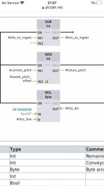
Thanks very much for sharing that @drbitboy. Much appreciated! I have another question just and excuse me for sounding silly but I am still learning, I just donā€™t understand the function of this ROL and the value loaded into it?
 
ROL is shift-left with wraparaound

So for Line 1-6 (Int this_line), the results of
ROL(2#1000_0000,this_line)
are in the following DAG* table:

Code:
[U]this_line[/U]  [U]Result of ROL(2#0000_0001,Line#)[/U]
    1      2#0000000[B][COLOR=blue]1[/COLOR][/B]
    2      2#00000[B][COLOR=blue]01[/COLOR][/B]0
    3      2#00000[B][COLOR=blue]1[/COLOR][/B]00
    4      2#0000[B][COLOR=blue]1[/COLOR][/B]000
    5      2#000[B][COLOR=blue]1[/COLOR][/B]0000
    6      2#00[B][COLOR=blue]1[/COLOR][/B]00000
               ^^^^^^
               ||||||
               ||||| \
               |||||  Line 1 bit
               |||| \
               ||||  Line 2 bit
               ||| \
               |||  Line 3 bit
               || \
               ||  Line 4 bit
               | \
               |  Line 5 bit
                \
                 Line 6 bit
Binary notation

2#bbbbbbbb (b = 0 or 1) represents the bits of a SInt (a.k.a. byte or 8-bit integer), LSBit* on the right, MSBit* on the left; "2#" is the radix i.e. that's how you declare the following digits (b's) are bits (binary digits).

* DAG => Dreaded ASCII Graphics
** LS => Least Significant; MS = Most Significant
 
drbitboy, some lazy people would like you to upload the project so they can play with it and learn some fancy shifting.


Thanks


Here's a convoluted one with a high speed counter. Needs polishing but looks promising. github link
 
drbitboy, some lazy people would like you to upload the project so they can play with it and learn some fancy shifting.


Thanks


Here's a convoluted one with a high speed counter. Needs polishing but looks promising. github link


Sure, but there is no shifting; I used @JesperMP's idea of a static array of bitfields with moving indices, which indices wrap around.


Is this right?

I have V14, so I doubt I can open .zap16.

- Monitor ("put on your glasses") [Main OB1]
- Modify HMI_Start_input to be 1 (program will assign it back to 0 a la "Set and forget")
- Modify run_simulator to be 1
- Watch current_pitch values (0 to 511) on Network 3
- Browse FIFO_bits.fifo_bits[current_pitch+delta]
 
Last edited:
That's great, thanks a lot.

I will move to 14 on the weekend but the main plot is very straight forward and can be implemented with a simple counter and compare instruction :

Tooth sensor , counts indefinitely in DINT and is allowed to rollover.
Trigger sensor, captures current count.
Lane number is entered manually
GoTo value = CapturedValue + number of counts to Lane
GoTov value and Lane numbers are stored in a two dimensional array. Every trigger the values are "inserted" into the array and it is then sorted in ascending order.
Counter current value is consistently compared to the counter value in the first array element.
When RV=CV (reference value in the array and counter value) the valve number in the second dimension of the firs element is actuated.
Array and tags are updated accordingly.

There are quite a few validation that have to be included to account for things like multiple valves firing at the same count value and with HSC it gets a bit messy but if the application requires a high resolution encoder, high speed and precision, using HSC is a good candidate.
 
Rolling over may be a problem, i'll have to rework that.

One approach would be to treat the array and the sorting as two groups: first group has RVs (reference value) greater than the current CV (counter value); last group has RVs less than the CV; items are sorted by RV within each group.

Probably the easiest way to program, but the most inefficient to run, would be to sort items the entire array, then repeatedly rotate the first RV to be the last until the first RV is greater than CV.

An alternative would be a wrapper around an insertion sort that knows the position of the first, if any, rollover in the array, and inserts new RVs that are not greater than the CV at or after the rollover position, and inserts new RVs that are greater than the CV at or before the rollover position. It's a binary search (to locate the insertion position e.g https://docs.python.org/3/library/bisect.html and https://reprog.wordpress.com/2010/04/19/are-you-one-of-the-10-percent/) either way, so it's fairly efficient.


Still, this RVs-only, variable-length array FIFO approach seems like a lot of extra effort to avoid empty space, compared to a fixed-length array that maps one conveyor-length + delta of the future of the process in an array that almost all empty space (zero bits) with just a few one bits..


Is similar to your thinking:
Have a DINT variable ROC(roll over counter) on every counter rollover.
Increase the array size to three domension: RV, ROC ( calculated for future count), LaneNumber.
Sort for RV and ROC


Both counters will count positive only, no rollover to negative. That should give me a lot of counter value to work with. Both counters would be reset at operation start. Depending on the mechanical specs, length of conveyor, encoder speed etc. , It may work.
 
Added HMI (thanks JRW!)Sidebar

Also, for anyone who got here via a search of The Google using some of these words:
System initiated request: - No or no valid data record for central device option handling,
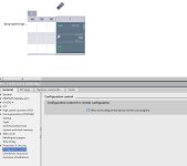
you may want this URL:specifically, uncheck the option shown in this image:
optionhandling.jpg
I was dead in the water and thought my S7-1200 had gone south until I stumbled onto that page.
 
Last edited:
Here is my suggestion, I have based it on what I understand, basically the code is no more than 50 lines I did in a bit of ST for the shift (although on my Mitsi simulator could have done it in all ladder or FBD & it could have been smaller as it has word and bit shift that's easy to use.
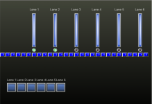
Not going to post the code as it is only a test but here is what I consider a one lane to 6 take off conveyors, the operator decides where the pack is going to be diverted to and presses one of the six buttons, this loads the shift register with the lane number, when it reaches that lane the register at that position is compared with the lane number an diverts the pack down that lane, not bothered to delete the value in the shift register as it falls off the end of the shift eventually.
As I said this is only a test and is limited to 28 shifts on the screen for demonstration but the shift register is currently 1000 words.
Here is a screen shot taken during the running & a couple of diverts working shown by a lamp being green.

Shift Trial.png
 
@parky; what happens if two or more valves need the same location in the FIFO?


šŸ™ƒ d'oh! Never mind, forgot which model this was .
 

Similar Topics

Hi I am fairly new to codesys 3 but I'm currently trying to make a little project using 4 cameras, a sensor and a conveyor belt each camera take...
Replies
7
Views
3,679
Posted previously but had the wrong info, hoping to get new advice. Being a mechanical engineer, I'm not very experienced with PLCs, and what...
Replies
7
Views
2,449
I'd like to start by saying that my background in engineering is mostly mechanical, and I have a tiny bit of experience with AB and RSLogix (to...
Replies
10
Views
2,648
Hello dear experts! just started learning STL and tried writing a program that writes the status of a particular bit M0.1 on 80 bits of...
Replies
2
Views
1,752
hello people, im totally NEW in plc. i'v read reference of ladder diagram (OMRON PLC CPM1A-20CDR). why do people use 253.14 as data input of...
Replies
6
Views
4,561
Back
Top Bottom