This morning... upload customer's Mitsubishi Program

AutomationTechBrian

Lifetime Supporting Member
Join Date
Jul 2013
Location
St. Cloud, MN
Posts
669
I'm leaving right now to go to a customer who needs me to upgrade their 2 network-connected obsolete VFDs. I haven't been there yet, but I have this picture he sent. I got the GX Works 3 software, and the comm cable, and this will be the first time uploading a program in the Mitsubishi world. I have from 10:00 to 10:30 Central time (USA) to do my thing. If anyone has tips, let me know. I'm being brief because I need to get out the door. I'll have internet access on the job site, so I'll check in if something is posted.

Mitsubishi.jpg
 
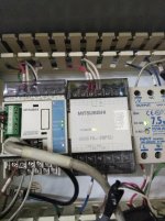
The chances are that it was done in GX Developer, so I suggest you upload the code using that session. It could have been done in other versions like GX IEC or even Works but unlikely and it is a small PLC so even if it had then they would probably not have downloaded the symbolic code to re-construct it.
This means it can only be uploaded as ladder or Statement list and no comments.
There can be a problem with GX IEC configured code as reading it back in ladder can display errors in the ladder i.e. you get a ladder rung with an odd contact that does not seem to connect and shows in yellow and cannot be converted to be able to download again. This was a bug in GX IEC, however it was valid in operation (I have come across this a number of times). Not all is lost as if you display it in Statement list you should be able to sort it.
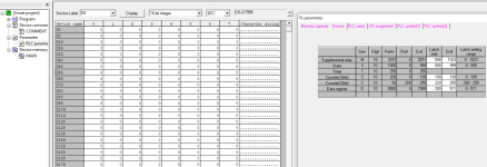
The other problem you may have that it has a password, this will not allow you to upload it. Edit: I noticed that it has a cable already connected to the port, this is possibly an HMI, Mitsubishi had a Badged version of Beijers HMI's until the Got series so it could be one of these, some models were able to use passthrough to program the plc, if it is one of those & it is configured a 232 cable can be used to program/monitor the plc without removing the HMI lead. Just another edit, when you create a new project in developer, make sure you select the correct plc, and in the project list there should be a heading called main, this is the data i.e. D0-xx, when you upload make sure you upload this as it will take a snapshot of the D registers, some are used for certain purposes like communications or special cards or other functions so that you have a copy of the data held in these, Basically, when you get the popup to upload, select plc program and data, possibly symbols (cannot remember) even if they do not exist it will complain but will upload everything that is configured.
 
Last edited:
Yeah, I'm guessing that is for the HMI. My thought is I would try powering down the PLC, unplugging the HMI, and plug it in the Comm cable and rebooting the plc. Then I would try uploading. What do you think about that method?
 
That's not a problem I wouldn't think. I have done it many times (although probably not the right thing to do I have left them powered up but I suggest you do power it down).
Just be careful plugging in the din connector I have seen people bend the pins & damage the port socket.
 
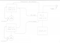
Murphy's Law... I drove over an hour and got there at 10:00, only to find out that they weren't able to stop production today. So... I took some pictures, and scoured the documentation to find the control drawings and the parameter list for the Mitsubishi drives. Looks like I have enough to keep me busy for a while. I'll get a little background on how communication is accomplished between the PLC and drives, and drive to drive. Then I'll go back and see if the upload is successful. I'll attach a drawing of the PLC/VFD connections, just for a little flavor.

Parky... thanks so much for responding. That was a lot of good information. I was contemplating whether or not to post, but it ended up being a good thing that I did. Thanks again!

Drawing.png
 
You could have actually taken the program out while you were there, running or not.
Unplug the HMI lead, it will complain of lost comms and plug in your lead.

GO 'online - 'plc model - 'upload from plc.

Then plug the HMI back in, it will regain comms again.
 
I agree with Ronnie, however, even though I have unplugged & plugged in on Mitsubishi probably thousands of times and never had a problem, to go to a site and on that one occasion something goes wrong that's a worry, however, powering down & up again is more likely to cause a problem, i.e. a spike at the moment you power up again, power supply failure (most PSU failures occur on power up).
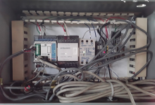
It looks like from the pics that this has a 422/485 BD add on board for the communications to the inverters, The settings for the protocol are in the 8000 range of registers (8000 > on are for things like clock, coms settings etc.
Just a heads up on communication with GX Dev. The FX if powered down defaults to 9600 etc. however the settings for the add on board are retained (battery or NVRam permitting) this is not a problem for most HMI's I have used and most people set the coms at the default, however, GX and some HMI's are capable of forcing the plc to other baud rates when you set the connection in GX even if you set it at a different Baud rate it will force the PLC to communicate at that rate, if the HMI is not capable of doing this operation then it will not communicate until you re-boot the PLC. I came across this when connecting an OPC server at 56k to the programming port it would not communicate, however, if I first connected GX at that rate then plugging in the OPC server worked, however, when powered down the plc reverted back to 9600, so I had to keep the server at the default.
It would be a good idea to download the add on board manual that shows typical set up of the board, this is often done within the plc code with TO/FROM instructions to the registers Here is a link to the manual

http://dl.mitsubishielectric.com/dl/fa/document/manual/plc_fx/jy992d69901/jy992d69901e.pdf
Note: section 4 gives the registers used and some examples, it's a bit lengthy but covers all versions of the add on boards.
If the original inverters are Mitsi i.e. 500, then upgrading them to the 700 it may not require any mods in the PLC as the 500 & 700 are so similar. but I have never done it.
 
You could have actually taken the program out while you were there, running or not.
Unplug the HMI lead, it will complain of lost comms and plug in your lead.

GO 'online - 'plc model - 'upload from plc.

Then plug the HMI back in, it will regain comms again.

I didn't even ask if that was possible. The Coronavirus has got them on edge. A reduction of operating hours was just announced earlier that day. The last thing I wanted to do is risk screwing up the production run doing an upload on a PLC I've never worked with before. I'll have plenty of time to work on this in the upcoming weeks. ...as long as one of the drives doesn't fail!
 
I agree with Ronnie, however, even though I have unplugged & plugged in on Mitsubishi probably thousands of times and never had a problem, to go to a site and on that one occasion something goes wrong that's a worry, however, powering down & up again is more likely to cause a problem, i.e. a spike at the moment you power up again, power supply failure (most PSU failures occur on power up).
It looks like from the pics that this has a 422/485 BD add on board for the communications to the inverters, The settings for the protocol are in the 8000 range of registers (8000 > on are for things like clock, coms settings etc.
Just a heads up on communication with GX Dev. The FX if powered down defaults to 9600 etc. however the settings for the add on board are retained (battery or NVRam permitting) this is not a problem for most HMI's I have used and most people set the coms at the default, however, GX and some HMI's are capable of forcing the plc to other baud rates when you set the connection in GX even if you set it at a different Baud rate it will force the PLC to communicate at that rate, if the HMI is not capable of doing this operation then it will not communicate until you re-boot the PLC. I came across this when connecting an OPC server at 56k to the programming port it would not communicate, however, if I first connected GX at that rate then plugging in the OPC server worked, however, when powered down the plc reverted back to 9600, so I had to keep the server at the default.
It would be a good idea to download the add on board manual that shows typical set up of the board, this is often done within the plc code with TO/FROM instructions to the registers Here is a link to the manual

http://dl.mitsubishielectric.com/dl/fa/document/manual/plc_fx/jy992d69901/jy992d69901e.pdf
Note: section 4 gives the registers used and some examples, it's a bit lengthy but covers all versions of the add on boards.
If the original inverters are Mitsi i.e. 500, then upgrading them to the 700 it may not require any mods in the PLC as the 500 & 700 are so similar. but I have never done it.

Wow, you are right on top of this, Parky! I knew I'd have to find the communication manual for the card they used. Thanks!

I'm very new to this project/issue. There is a background story that I'll share...

The Mitsubishi PLC and drives were a retro-fit on an older machine. The process needs line speed to be matched by both motors, which of course the drives can do well. Sometime in the last year, one of the drives went down. That drive is obsolete. My senior (but old-school) tech found a replacement on the after-market and installed it using the parameters from when the machine was updated. The new drive had faults/errors that were a result of newer firmware. Fortunately, the problem on the old drive was on the power board, and he was able to swap control boards and get everything to work.

Everyone realizes they were lucky. Next time they lose a drive it could be much worse. So they asked if I'd like to look at updating the hardware. I know I'll put more time into this than I could possibly bill them for, but like a lot of us here, it's not all about the money. I see this as a great opportunity to learn about the Mitsubishi software and hardware.

I have a couple of other customers with immediate issues to address, so I'm collecting information and scanning everything until I can sit down and focus on it. I'm contemplating the drive-to-drive connection. I'm thinking it implies that one of the drives serves as a master. Any thoughts about the registers that would govern that communication?

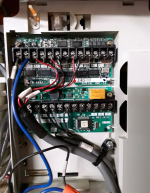
I'll post a couple of pics, just to add more flavor...

DriveTerminals.png PLC.png
 
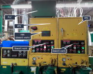
Oh... one more detail. The HMI is bad. It hasn't worked for years! ...Can you imagine?

The machine is still very productive. They want to make sure they can keep it running.

Controls.png HMI.png
 
First of all the HMI is a Beijers (possibly badged for Mitsi) and it is now obsolete
There was an updated version E10xx (E1000 range but these are now obsolete) so I guess this system is 15-20 years old. It looks like the inverters are Mitsubishi but very old, not sure what model they are. If they have the money it may be worth thinking of upgrading everything but that's probably not going to happen. As for the Registers, there will be the D8000 range where the protocol are set & other relevant control. but there is probably some code that writes values from a lower range of D registers. Unfortunately I cannot see the actual PLC number it could be FX0n, FX0S, FX1 etch. they do have different ranges for the registers. For example the FX2N has useable Registers from D0 To D511 and as standard D200 to 511 are retentive, but this range can be changed so it is likely that if it is a FX2N then registers D200 > may be used to hold speeds etc. and probably moved into the buffers, It has been some time since I used inverters via coms (I prefer to use analogues & I/O) I do have a project somewhere that had 5 500 type inverters on coms, will try to find it out. Edit, When you upload the code select plc parameter, Device memory (it will ask you to give a name for the Device memory I think the default is Main so use this) and program. The parameters when selected in the tree will show you the settings for latch areas etc. and the Device area will contain the data snapshot.
 
Last edited:

Similar Topics

I get to start my day be trying to figure out a no water situation in my my house. Submersible pump 3 wire pump. I opened up the control box...
Replies
33
Views
8,411
SO I retrofitted a 4 headed filler machine a while back. It had a SLC 4 and an old off brand HMI screen that didn't work. I upgraded to a...
Replies
20
Views
3,271
https://productforums.google.com/forum/?hl=en#!msg/chrome/mdfxZTiTvTc/xxyGydWSIfEJ TWO DAYS! The wireless kb and receiver (placed out out of...
Replies
10
Views
3,456
Hello, I have two micrologix 1000 and I'd like to hook them together much like you can with PLC5 and SLC 500 where they share the same program...
Replies
4
Views
2,481
Back
Top Bottom