Reading Analog from 1747-SN

Ranjith

Member
Join Date
May 2007
Location
Melbourne
Posts
316
I just added a 1746-NI4 in remote rack slot 9 and ch0 is set to 0-10V input. Now I am trying to read the AI and the value getting back from BTR is a big negative number. I am trying to send a BTW to configure the channel and the BTW comes back with -9 error code. Can someone please guide me in the right direction. 1747-SN is in slot 17.
Thanks in advance
 
Thank you for posting the screenshots and the program !

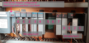
Please describe carefully the physical slot numbers and chassis arrangement in the remote chassis.

The A-B terminology of "Rack, Group, Slot" is carried over from the old PLC-2 controllers and universal remote I/O from the late 1970s, so it can get a little confusing.

In general, with the common "1 slot addressing" format, the term "Group" means the physical slot number to the right of the Adapter comms module, and "Slot" is zero for all modules.

The first 8 I/O modules would be Rack 0, Groups 0-7.
The 9th I/O module would be Rack 1, Group 0.


Your block transfers are addressed to "Rack 1, Group 1, Slot 0", which is actually the tenth module.
 
Thanks for the reply Ken.
It is the 10th Module if you count the Adapter module as the 1st one.
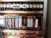
Please see attached photo. NI4 is the last module on the right.

Resized_20200403_093143.jpeg
 
Thank you for that clarification. That does make the 1746-NI4 "Rack 1, Group 1, Slot 0", at least in typical 1-slot Addressing mode.

I should have annotated on the screen: those are "Group" numbers for these modules in RIO 1-Slot Addressing Mode.. In 1-slot addressing, the "Slot" number is always zero.

The -9 error code is typical of a BTW to a module that doesn't support them, or that contains invalid configuration data.

I'm not sure what the problem is, but I'll take a closer look at your program.

Annotated_Slot_Numbers.png
 
Last edited:
The NI4 is compatible with the SN. The data you send to it would match up with the same bit patterns and length if you drop a NI4 into the SLC IO rack using the SLC O: and I: tables. Now if you drop one into a SLC IO rack you will see that it has no output data and only the four input words. This is because the NI4 channels are configured using the switches on the module so there is no configuration needed.


In conclusion you don't need any BTW just a simple four word BTR and your done. The scaling will be the same if you had it a SLC rack.
 
Of course, thanks.... the old 4-channel analog modules did have just 4 words in the ordinary backplane I/O channel, and didn't need any configuration data.

You can't get more than 2 words of data per module through the discrete image on RIO (and that's half-slot addressing), so you need a BTR to read the 4 words.

The data should be just 0-4095 in each word. I wonder where the negative number is coming from.
 
Thanks for the help.
So the BTW is not required for NI4.
I will double check that the DIP switch is off for Ch0 tomorrow.
 
I was mis-remembering the analog range for the 1746-NI4. It's a 16-bit module, so if it's configured for a bipolar voltage input (like -10 to +10 V) you could see a negative number.

NI4_Ranges.PNG
 
Thanks for your help Ken/JaxGTO
It's all good now.
We had the polarity wrong.
Now I am getting the correct positive value thru BTR.
BTW is not required.
 

Similar Topics

I am setting up a new system and have an s7 1214 plc with an sm1231 4x AI (6ES71231-4HD32-0XB0). It is configured for 0-10v and has no faults in...
Replies
5
Views
1,130
I'm pretty new to Siemens. I just downloaded a new program into a new S7-1500 CPU. All modules are ok/not faulted. here is the problem: i have 4...
Replies
7
Views
2,914
I need some help. I have a 1769-IF4 analog card that is hooked up to strain gages, the gages give a 4-20ma signal to the card. We had an...
Replies
9
Views
2,024
Hi all! Is someone can help me to understand what they means ? This is the only info I could find on my device : With this module is possile to...
Replies
5
Views
2,346
For the first time I have a load of analog signals being transferred into my Control Logix system via Modbus. I have sent analog to a DCS via...
Replies
1
Views
2,913
Back
Top Bottom