tank high level pump control

risk

Member
Join Date
May 2020
Location
california
Posts
3
New to group

I've seen well pump controllers with analog circuits that pump till sensing a current drop then start a timer.

Seems an opportunity to use a PLC to sense high water and latch a relay to pump until unloading is sensed by current drop and then deactivate the coil. This would eliminate the low level float switch.

I'm starting from scratch but happen to have a lot of Siemens equipment on hand. Was tempted to offer my code here as a starting point for discussion but that would be embarrassing.

As for the input. I was thinking of a sense coil into a/d module and tuning in S7 but wonder if there is a turn key module for this problem. I prefer to use modular hardware for learning.

Thanks for helping out a beginner.
 
embarrass yourself first.


"the quickest way to get the right answer on the 'net is to post a wrong answer."


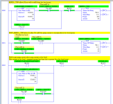
there is no way it needs to be this complex:

xxx.png
 
Last edited:
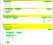
Is this better, or still too complex? It does more (added start/stop/seal-in circuit) with fewer instructions, and only one timer. I wonder if there should be an [XIO MANUAL_START_NO] or [XIC WANT_PUMP_ON] in front of the timer, or maybe remove the REFILL_TON/TT seal-in, so any reset of the low-level event proxy also resets the REFILL_TON timer.


[Update - There is an edge case that fails*: if the low-level event proxy does not clear in the last 2s of the refill timer, then the timer will never reset and the pump will mever auto-restart, at least until the high level switch goes to 1. So there needs to be an [XIO REFILL_TON/DN] so the timer done bit will reset the timer; also, the REFILL_TON/TT seal-in is redundant, given the logic in rung 0003.


* It could be argued that this is an exception, and not a failure, requiring operator assessment and intervention because the pump current did not go high enough after allowing 20s (or whatever time was chosen) to refill the well, and the REFILL_TON/DN bit should instead be redirected to drive an alarm]

xxx.png
 
Last edited:
Wow! Drbitboy, Thanks for your thoughts and your clear style. My first approach used functional blocks but I see professionals use ladder logic.

I misstated the requirements however. This is not the well recovery problem I mentioned as an example of the current sense but a simpler tank pump-out when full problem. Sorry...

After If I striped out the timer refrences it seems to me that you could clean it up better.

Have you had any contact with Structured Control Language (SLC)?
 
If you want to use FBD then the bit of code below is a starting point. I notice you are thinking about using Siemens I do not have it on this PC but this is something like it would be. Use the internal Functions for scaling the raw analogue level (you don't have to but it is easy to see a tank level in say 0-100% rather than a raw value of 0-16384 or what ever the raw value is).
This is a simple start/stop of pump and no alarming, there are caveats due to some unknowns, for example normally you would have safety limits i.e. low low & high high digital signals for safety i.e. stopping incoming pumps if high high level reached & same for low low level. you could use timers so if the pump runs for x amount (more that the expected time to empty or incoming pump running for more than expected, however, it depends on if you have any control of the incoming pump or supply, and if the incoming may continue while pumping out, this would make using strait forward alarm timers doubtful so below is just a pure start/stop of the discharge pump.

Level Control.png
 
Wow! Drbitboy, Thanks for your thoughts and your clear style. My first approach used functional blocks but I see professionals use ladder logic.

Not at all, I am a programmer with a new toy (language), and not at all a PLC professional; most of what I do is trying to learn by bumbling around making mistakes among tolerant forum members who are far smarter than me.


the real professionals are the folks here that tell you, "oh, you need to upgrade, that didn't work until around March 15 at 12:34:56 UTC when version 32.x.z.q.j-1/snuffleuppagas came out." From memory.


I misstated the requirements however. This is not the well recovery problem
Ah, then parky's last two rungs are what you want: latch/set on low current (low level/cavitation proxy); unlatch/reset on high level switch event. It could also be done without Set/Reset and a single --( )-- to the pump, but that is an academic exercise.


maybe add start/stop/seal-in circuit for auto/off.


I have seen SLC (SCL?) - isn't that the same as Structured Text (ST) - but I have not fiddled with it yet Anyway, I have written buckets of Python, so SCL/ST seems like cheating when I am trying to learn summat here.


That said, I think the Set/Resets needed here map to a pair if IF-ENDIF clauses:


Code:
 IF MEASURED_CURRENT_WORD < MAX_CURRENT_AT_LOW_LEVEL_WORD THEN
   // Turn pump off if current goes low
  PUMP_ON := 0
ENDIF


IF HIGH_LEVEL_BIT AND PUMP_IN_AUTO THEN
   // Turn pump on if high level switch indicates, well, a high level
  PUMP_ON := 1
ENDIF
? I am not familiar with the exact syntax but that's the basic idea. Code golfers would do it with a one-liner, of course:


Code:
PUMP_ON := ((CURRENT >= MAX_CURR_LO AND PUMP_ON) OR HIGH_LVL) AND PUMP_AUTO
That saves vertical real estate on the screen** but takes a few extra ms to grok; so six of one ...


** an especially critical resource in TIA; can anyone do real work in that enviroment without multiple large monitors? rotated? man, I find that layout annoying;)


Anyway, sorry for the rant, looks like it will be an interesting day.
 
Forgive my late response. This place is an amazing resource.

My next day off I am going to get my head around this.
 
It is simple logic, the only caveats are if the tank you are emptying is being filled at the same time, this could be overcome by using a timer & if it does not reach the low level within a given time then shut the discharge pump off & alarm or just assume this is the case and just shut of (reset) the pump bit.
The code is for emptying, just change the SET & RESET bits over for filling.
The code might look a bit different to what your PLC displays i.e. ladder FBD ST etc. but in plain English it's
Tank fills, when the level is equal or greater than the high level set point then set the pump run bit.
When the tank level is equal or less than the low limit set point then reset the pump run bit.
Just reverse it for a pump that fills it.
You do not have to use a >= function you could just use > (Greater than) or < (Less than) function, I suggest you do not use an = (Equals) function as depending on the scan time and analogue conversion the value that appears in the PLC may jump a digit or two and you will miss the point when it equals.
 

Similar Topics

I am looking for a device that can detect high level in a tank that holds liquid (hot) wax. I have not worked with any systems that have liquid...
Replies
14
Views
5,507
Hi All, I have been trying to adopt some of the HPHMI/Situational Awareness philosophies in my recent HMI designs and I've always been unsure...
Replies
10
Views
3,626
Hello PLCS.net! I wanted to ask someone who has experience in this. How does one do fluid level measurements if it's a safety/environmentally...
Replies
7
Views
2,172
Does anyone have RSLogix 5000 ladder diagram program of tank leveling (factory IO). Fill valve, discharge valve, set point, level, etc? I looked...
Replies
2
Views
147
Back
Top Bottom