Programming multiple moves of a hydraulic cylinder?

thinksabunch

Member
Join Date
Jul 2013
Location
Tempe, Arizona
Posts
18
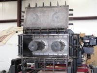
I’ve converted a hydraulic log splitter into a block press – see pictures of press. The blocks are made from paper pulped in water with a hardener added – see picture of blocks. The hydraulic cylinder (pushing a big rectangular piston) presses a block by going through the following steps - starting from the fully retracted position:


1.1) Mix is dropped in a preweighed batch through the top of the press via an auger (picture) to a location just in front of the piston
2.2) The cylinder starts moving forward at a (higher) speed until the mix is entirely enclosed in the pressing box – the mix is being squeezed between the front of the piston and the inside of the front door of the press
3.3) Then the cylinder is slowed to another speed (by half or more), but still moving forward – we’re squeezing out water slowly while pressing the pulp into a block
4.4) Then the cylinder is stopped because it has reached a position in the press where the block is four inches thick – pressing is done
5.5) Then the cylinder is reversed about an inch and
6.6) stopped to take pressure off the front door
7.7) The front door is opened
8.8) Then the cylinder is directed to press forward again and it pushes the block out of the press four inches – the piston actually almost totally exits the front door of the press
9.9) Then the cylinder is instructed to fully retract as fast as it can
1110) During retraction, as soon as the piston is inside the front of the press , the door is closed
1111.) The piston quickly reaches its fully retracted position and the process starts over again.


A proportional solenoid-operated hydraulic valve can handle forward, stop, reverse and speed changes of the hydraulic cylinder, but what Is the best approach to take with a PLC? Right now we’re performing these steps manually and throughput is slooow. Is there a way to set up timers, limit switches or some other method? A rod connected to the rear of the piston protrudes through the back of the press and moves back and forth with the piston. So it would be possible to set up limit switches where appropriate in the sequence - but I would prefer to do it in a way that doesn’t depend on many externally mounted parts or switches - because of vibration, weather, exposure to damage, etc. All of this is done outside in the weather.

So, I would very much appreciate your advice on the best way to approach this problem.

Thanks.
Barry
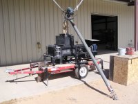
augerandpress400 copy.jpg BetR-bloks 400 copy.jpg presscavityfromfront 400 copy.jpg
 
Hello Barry.

Is this the same project you were inquiring about the IDEC PLC for?

What kind of positioning precision do you need?

I recommend using a Temposonics or Balluf magnetostricitve position sensor. These sensors are widely used in hydraulics and are typically mounted inside the hydraulic cylinder but there are externally mountable models available as well. I use a lot of both brands and find them to be highly reliable even in harsh conditions.

Since you are new to PLCs I have a different suggestion for you. A Delta RMC70 will do everything you have described. The configuration will be a lot simpler, all you need to do is fill in a table of lines that describe each move you want to make, direction, speed, and distance, and any timing you want such as dwell times, etc. The RMC70 with an MDT will cost you a little bit more than a micro PLC + limit switches, though not a lot more. But the time it can save you is quite a bit.

I want to address this statement of yours though
Right now we’re performing these steps manually and throughput is slooow.
Is the throughput slow because the manual operation is slow and you are having to stop and make manual adjustments, or is it slow because the machine is slow? If its because the machine is slow then a controller isn't going to make it run faster. You will see some small gains by eliminating the human factor, but not much. For fast operation a hydraulic system designed from the ground up will be the way to go. There are several of us here that have extensive hydraulic backgrounds so you've come to the right place.

Just curious, what are those blocks used for?
 
Aha, I found your video. That's a lot clearer now. 'Fuggetabout' what I just said.

Position sensing can be done with round shaft collars that are positioned on the rod. The collars can be sensed by proximity switches. You can use just one collar and a few adjustable proximity switches or a single proximity switch with multiple adjustable collars. Proximity switches are sealed and won't be affected by the weather, dust, or moisture.
 
Oh, cool, this the the BetR-Blok project. You do neat stuff !

Since you're just prototyping the machine, saving a few dollars on the controls isn't nearly as important as getting controls that work effectively and safely.

A linear transducer is a really good idea. We've been using these "Temposonics" style in the timber business for decades: they're strong, durable, and accurate.

A press like this is a nightmare installation for mechanical limit switches or for inductive proximity switches. I guarantee you will have one or more of them sheared off by a proximity flag, smashed with a hammer, or used as a boot-cleat-cleaner within a week.

Maybe you just need one of the less expensive linear transducers with a simple 4-20 mA or 0-10 V output. That would give you an easy way to bring the input into a micro PLC.

It's nearly impossible to do something like this with timers. Don't waste your time.

In my opinion, the ability to get spare parts quickly and have somebody fix the controller if it breaks is far more important than the price of the controller. Walk into any technical college in the USA and you can find somebody who can program an Allen-Bradley controller. Probably 50% of the time you can find somebody who knows Automation Direct. With IDEC that would fall to under 5%.
 
You probably don't want to replace the cylinder in your ram, though, so maybe the internal Temposonics isn't the right approach.

The least expensive kind of linear measurement is a "linear pot", which changes resistance as it moves. It's not nearly as accurate as a Temposonics style, but it's a lot cheaper. You can use it directly as a voltage divider circuit, or run its output through a signal conditioner.

I wouldn't try to use a "string pot" type transducer in this application; they're too likely to get hit by mud or debris.

Could you rig something like this to your ram ?

http://www.pennyandgiles.com/Products/Linear-Position-Sensors/Linear-Displacement-Sensor-SLS320.aspx
 
Yes, I was the one who wanted general info. on IDEC. The local reps. seem able and cooperative.

"What kind of positioning precision do you need?"

The only step in the sequence where positioning is somewhat critical is the first "stop" location. That controls the thickness of the block and should be close. I think if we can stop the cylinder within plus or minus .2 millimeters (that's about a 1/64th inch total range), I would be happy - probably ecstatic. In reality, probably plus or minus 1/64 inch would work.

.."externally mountable models available as well..."

I am going to need a stroke of 30 inches and I plan to build these systems once I've refined the one I'm working on. I'm under the impression that internally mounted devices cost quite a bit so i think I will probably stay with external devices. I would hope that then I could use any manufacturers 4-inch cylinder I want, correct?

" A Delta RMC70 will do everything you have described"

The entire process I want to control includes the hydraulic cylinder motion control but also control of mixing, loading, door opening/closing and a few other things - so does the Delta make sense in that wider context?

" For fast operation a hydraulic system designed from the ground up will be the way to go. There are several of us here that have extensive hydraulic backgrounds so you've come to the right place."

I was hoping to hear that, yes! The mixing and loading are going to have to be controlled hydraulically too. Right now I do everything manually with electric motors and weigh scales. The liquid mix is measured by volume - eyeballed in a tip-able box. Many of the steps are done manually, which is why throughput is slow. The press itself is capable of full stroke forward and back in about 11 seconds. But to load manually or from auger (top it off manually, run the press manually, stop, reverse, open the door, press out the block, reverse the press, shut the door, lock it, start loading again....many of these steps require being at different locations around the press, climbing up, down, moving to the front and back. That's what slows everything down, not the press.

So I have been manually operating everything through the prototype development stage and now I have to design for speed.

"Just curious, what are those blocks used for?"

Our motto is "Building Homes By Saving Trees". We are working our way through the accreditation process to gain approval to use these blocks to build buildings. They are composite cellulose/binder blocks with good insulating quality. Basically making them with recycled paper. I have a website where I show how to DIY as well. LivingInPaper.com

Thank you for responding and yes I will be happy to hear any suggestions related to hydraulics. I have come to the conclusion that that approach is the best.

Barry
 
I was hoping this could be the case. The rod is protected inside the frame of the press so not too exposed and I could even add a little cowling. But will proximity switches come on consistently enough to keep the STOP (block thickness)within plus or minus .2 millimeter or at worst plus or minus 1/64 inch?
 
Hi again Ken,

Forgot to answer your question. My press is already set up with a rod attached to the back of the piston which travels with the piston. It is purposefully located in a sheltered location behind the frame of the press and could be made even more sheltered if necessary. I was hoping to use what I have and just add a collar and limit switches. But I am concerned with the STOP for thickness. How accurate are limit switches? do they come on at different distances from the collar? or are they consistent? Thanks Ken.
 
Thanks for the additional details, especially about the final stop position precision.

I would recommend using a low-precision linear potentiometer in addition to a single proximity switch and inductive target (probably a collar).

Not having multiple collars and switches makes most of the damage, maintenance, and logic problems associated with them go away.

You can use the analog value from the transducer to control the speed and stroke for most of your functions. When the transducer shows that the ram is within a short distance (maybe an inch or so) from the final target, you switch the hydraulics to very-slow mode and stop right when you hit the inductive proximity switch for the end of compaction. Using a collar and inductive prox gives you a good physical assembly, and means you can drive right past it to push the block out.
 
Proximity switches with collars as flags would probably be the least expensive way to automate this ram. The drawback is that they can be tricky to adjust, are moderately prone to damage, miswiring, or mis-installation, and do not provide speed, direction, or continuous position feedback.

My count of the positions the ram needs to detect are:

1. Fully Retracted
2. Pressing Box Entry
3. Pressing Box Final Position
4. Pressure Relief Position
5. Piston Clear of Door
6. Fully Extended

You could probably combine function #3 and #5, so that the controller senses the piston retracting past the Final Position switch and knows it's clear of the door so the door can be re-closed. The cycle time penalty for that is small.

And you could probably use a timer for function #4; the amount of retraction to relieve pressure on the block does not sound like it needs to be precise, so it could be 1 inch or 1/2 inch or 1 1/2 inches.

But an analog positioner would give you a continuous feedback value so you could just compare the distance measurement to a programmed value, and you would know function 1, 2, 4, 5, and 6. You also can calculate speed, so if you had to change the hydraulic output to account for fluid temperature in the morning or in the winter, you could. Because you have continuous feedback, you would know very quickly if the ram jammed, rather than having to program timeout logic based on when a device was triggered.

I think you would still want a proximity switch for Function #3, the Final Position.

The sensing field of a proximity switch can be tricky: the field is basically parabolic, so the distance from the sensor to the target can change the position at which the sensor turns on. Some are more accurate than others; you will want to get a basic unit with an indicator LED on the head and experiment with it a little. Proximity switches come in many sizes and shapes, but a common one is a 30mm or 18mm threaded tube, so you can put it in a nice threaded block and use jam nuts to fix it in position.

Is the rod that moves along with the ram guided with a bushing (heck, even a split nylon block) at the far end ? If it's just sticking out, I'm concerned that if it is bent or sways with motion that your flag is going to change its distance from the proximity switch. That would be a problem with a limit switch or with an inductive prox: it's just geometry.

Proximity switches can be a little more delicate than some mechanical limit switches. I've seen a lot of busted prox heads, but probably more busted or bent limit switch actuating rods or lever arms. The nice thing about a collar as a proximity trigger flag is that they're difficult to bend or break.
 
For an inexpensive linear transducer we use these sensors from Balluff. The senor comes with a 0-10V or 4-20mA output. For high precision I use Temposonic MDTs with SSI outputs, but you don't need that or the added expense. However, if you are going to build future machines I strongly recommend that you consider using an in cylinder MDT because of the extreme durability of that type of sensor.

I think you can position reliably for the prototype with a prox switch, especially if you use the leading edge of the shaft collar to trigger a deceleration and the trailing edge of the shaft collar as your final stop point.

The biggest advantage to shaft collars and a prox is that the positions are easy to adjust in the field and don't require any specialized know how. The biggest disadvantage is the same thing, they are easy to adjust by anyone, including someone who doesn't have a basic understanding of what the machine is supposed to do.


I'll second Ken's recommendation on the PLCs. If you are going to distribute these machines then an AB Micrologix PLC would be my first choice, probably a ML1100, just because of the market saturation you'll never have trouble getting parts or finding people who can work on it.
 
If you do use a MicroLogix 1100, there are two built-in 0-10V analog input channels on the controller.

They are only 10-bit resolution, though, so you get 0 to 1023 'counts' in an Integer register inside the controller that are relative to position.

Over a 30 inch stroke, that's a resolution of about 0.029 inches. That's enough to get 'pretty close' but I would still use a proximity switch as the actual in-position flag because you're looking for +/- 0.0156 inches.

Your choice of linear feedback device can be another discussion. While resistive sliders are very simple and inexpensive, they do eventually wear out (50 million cycles is very optimistic) and they do vary a little with temperature.
 
I would be a bit concerned about using hydraulics to achieve that kind of accuracy unless the moves are extremely slow.
The positioning suggestions above will probably work fine, but over the long haul the valves will become the weak link. The response time of the valves will vary with conditions such as temperature and wear which will cause the stopping distance to change.
 
One of the things I like about the Balluff BIW sensor is that inside it uses a non-contact sensor that rides over a circuit board with an exciter trace etched on it. Its a drop in replacement for a pot without the problems that a pot comes with. I mentioned it only as an inexpensive linear transducer. I still recommend using an in cylinder MDT for a second generation machine.
 

Similar Topics

Hello All, Merry Christmas, Happy Holidays, and Happy New Year to all. This is my first time posting. I've been reading these forums for the...
Replies
3
Views
3,377
Hi All, I am new to this forum and also new to AB PLCs. I have plan to get ControLogix, PLC5/20E, SLC5/05 and MicroLogix PLCs for testing and...
Replies
6
Views
16,518
Dear all, I have fx2n plc on my hand but I don't have the programming cable sc-09 and it would not be easy for me to get one. I need the cable...
Replies
3
Views
77
Hi all, i am the new controls guy at the plant and i have inherited a pc from the previous controls guy with Siemens tia portal version 16 and 17...
Replies
20
Views
792
I need to pull the program off of an old 90-30 so I can convert it to Allen Bradley. This is my first time messing with GE and I don't have the...
Replies
2
Views
83
Back
Top Bottom