anthr_plcnewbie
Member
Hi,
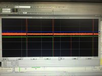
I need some help understanding the PID loop functionality in Powerflex 700 VC. I did some trend capture on encoder speed feedback (green), PI error (red), PI speed reference output (blue). Don't mind the three troughs as they were legit downtime in the line.
I don't understand why the PI error (in red) dropped off around 2am all of a sudden with no change in feedback or the reference signal. I would assume the PI Error changing when either feedback or output changes. Any ideas?
Thanks.


