Cutting accuracy can't meet with AB Servo Motor

Osias1970

Member
Join Date
Sep 2010
Location
Singapore
Posts
12
Hi...
I am using AB MPL-B540K with Kinetix6200 and CLX 1756-L72, 1756-M03SE sercos interface for flying shear application cutting metal sheet with setpoint 2400 mm. Line Encoder 20000PPR/RS422 with 500 mm circum of measuring wheel. Line encoder connected to K62000 auxiliary encoder input.
We auto tune the servo with dumping factor 0.8 and machine run with cutting accuracy vary from 1.2 - 2 mm. Customer expect to have cutting accuracy below 1 mm. High speed task 2 ms with priority 5, sercos connection 250 micro second.
Is anyone can help us for idea to solve this issue?
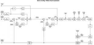
AB Servo Config Motor Dual Command.jpg
 
You can get some clues about what is causing cut length variability by looking at a trend chart of some key process and machine measurements. To start with, I would look at the reference/ master speed (line encoder), cutting assembly tracking speed, cutting assembly cut speed, and cut trigger.

One question about design: Is this application using electronic gearing between the line reference and cutting assembly tracking? Or position/velocity monitoring and motion commands in logic?

Some questions about this information that can help with troubleshooting:

. Is the reference speed (line encoder) smooth or noisy?
. Is the cutting assembly tracking speed up to reference speed before cut trigger?
. Is the cutting assembly tracking speed matching the reference speed (good control)?
. Is the cut complete before cutting assembly reaches end of travel?
. Is the cutting assembly "home" before the next cut trigger arrives?

These questions do not need to be answered in a reply, they are some aspects of the application to examine to explain the variation you experience.
 
Good questions Mispeld but isn't the problem that the RSLogix trends don't update fast enough? How fast can the RSLogix trends update.

I doubt the line speed of the encoder is noisy. The usually the problem is a lack of resolution or quantizing error. The higher the resolution the finer the velocity and acceleration error can be. The motion controller should be able to estimate the reference or master's position, velocity and acceleration. The position is easy but estimating the velocity and acceleration is not. Gearing to position only will always resulting in following errors.

The cutting assembly not only needs to match the reference speed but also the position. Simple gearing will not suffice.

Getting 'home' is old school thinking. This should make no difference. The key is the master and slave getting synchronized at the correct positions and matching speeds.
Stopping at home kills momentum and wastes time slowing to a stop then accelerating again. It is more efficient to be accelerating through 0 speed. This shortens the stroke reducing time and energy.

The cutter usually has a small area travel where the cut can be made. The cuts should always be made in this area.
 
I’m not one to explain the intricacies of motion control or how a motion controller ciphers’ every variable. But I thinking out loud and here are my thoughts for what they are worth.

Mechanically, we are talking a variation between 0.047” to 0.078”.
Assuming those are your highest and lowest? Your average cut length is 0.063”.

On paper, you are 0.008” above your high tolerance, a bell curve chart of 100 cut lengths would say where you actually are.

Are there any gearboxes in the drive system?
Were their REAL WORLD gear ratios factored in? Just because a gearbox SAYS it’s a 10:1, in actuality it could be 10.25522577:1. Figuratively anyways.
Are the gearboxes filled correctly with the correct oil?
Stiction maybe?

Brand new install or retrofit/upgrade?
If the latter, it would all make sense. The customers equipment wasn’t cutting correctly and they thought the fix would be to stick a servo on it.

None of this may mean a hill of beans in your application but it is what first came to my mind.
 
You need to have a multidisciplinary technical approach to solve problems like this. Can't just look at the control of the servos.

In my experience it's possible that it's the measuring wheel slipping on the sheet metal that is the problem. 2mm on 2400mm length is roughly 0.1%. That's not a lot when you measure.

Servo accuracy should be enough to handle this if the design is mechanically sound. Gearboxes? No, servos directly driving ball screws would be more like it.
 
Osias1970: Please recheck and measure your measuring wheel once again this has to be 500 mm exactly, not 500,02 mm or something similar. Use diameter measurement, check for roundness.
Are you using a pinch roll pressing against the metal sheet and encoder attached to it ?, this way you avoid slippery of tracking wheel.
 
2 ms is way too long to get precision. So makethe proces separate from the rest and approach it from the encoder and fill in the speed of the beld.
 

Similar Topics

Hi all, Im having a weird problem with my panel and i think its the plc causing it but it could be some other component. When i power up my...
Replies
10
Views
2,474
Hello all, We have a log oven with aluminium logs of 6m . I am trying to understand the program . THe log oven cuts the log according to the set...
Replies
4
Views
1,942
Good Morning , Do you folks know of any Laser Manufactures that excel in the cutting of plastic film ? We are looking to upgrade our...
Replies
0
Views
1,371
Greetings Everyone, I am currently writing a program that controls a chemical reactioin chamber. At a certain point I need automatically control...
Replies
25
Views
4,407
Hi everybody. Please see the attached image for the problem overview and share your ideas. All help will be greatly appreciated. Thanks.
Replies
7
Views
2,059
Back
Top Bottom