How can i elaborate this address in RSLOGIX 5000

turbohamad

Member
Join Date
Jun 2009
Location
Multan
Posts
108
Hello Experts;

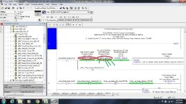
Good day. Here i attached a pic in which address shows how can i elaborate this address and reach the specific module?


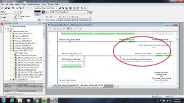
In some rung (L)--(U) bits are in series how can i understand this?

Regards

ladder.jpg Latch_UNlatch.jpg
 
You could make your pictures clear.........characters are unreadable...

For the second part, CLX allows more than one output per rung line, although it does not look clear : it means that if the preceding conditions are true then the various outputs are set/unset depending on the action requested. Read it the same way as if there were more than one output branch on the RHS of the rung.
I cannot elaborate on your specific example as I cannot read the text in the picture.
 
(1) How specific bits get addressed varies by card type. In your I/O tree there will be a rack named "UNREADABLE" (since we can't read you posted images clearly).

In the controller-scoped tags, there may be several tags, like UNREADABLE:I, UNREADABLE:O, UNREADABLE:3.I, UNREADABLE:3.C, and so forth, again depending on the type of I/O rack and modules within that rack.

Again typically, for discrete module, the tag UNREADABLE:3.I might be an alias for UNREADABLE:I.Data[3]. That is, the DI card is in the 3rd slot (which may or may not start counting from zero) of the UNREADABLE rack.

The various inputs on that I/O module will be the bit number of the associated word. Both UNREADABLE:3.I.5 and UNREADABLE:I.Data[3].5 reference the same point, and either can be entered in RSLogix.

(2). In RSLogix, the following two rungs are functionally identical:
    X        A
---| |---+--{L}-
|
| B
+--{U}-

    X        A      B
---| |------{L}----{U)

Some programmers prefer the latter style, others prefer the former, more traditional one. The rule is quite simple: output instructions always "pass power" if their inputs are true.


You may even run across instances where output instructions (coils, timers) are in the middle of a run, like so:
    X    +----- TON -+   Delay.DN     C  
---| |---| Delay |------| |------{L}
| 1000 |
| 0 |
+-----------+


When X is true, the timer runs. While the timer is enabled, it evaluates as "true", and so the only thing that is keeping the 'C' bit from being latched is that the timer is not done yet. Once Delay.DN evaluates as true, 'C' latches.

Again, this is more of a programming style. Programmers who have done more Function Block programming will be comfortable with it. Those who think of ladder as an electrical diagram, and don't feel that the timer can work without being tied to the "common" power rail on the right will get confused.

HTH
 
Last edited:
turbohamad said:
...how can i elaborate this address and reach the specific module?...

Right-click on the device tag address and select "Monitor...". This will take you to the "Controller Tags" which will show the tag within the tag structure of the module you are looking for.

turbohamad said:
...In some rung (L)--(U) bits are in series how can i understand this?...

As mentioned, in Logix 5000 controllers, there is the ability to place multiple output instructions in series on the same rung. Once the preconditions to the left are true, each output instruction is simply executed and then the "rung condition out" from the instruction is set true. This means the "rung condition in" is then true for the next output instruction and so it may execute. Unless the tag addressing assigned to the output instructions on the same rung are the same, or related in some way, then each output instruction's execution has no direct manipulation over the other output instructions on that same rung.

In your screenshot, it appears to be common Automatic/Manual change over logic. When Auto is latched (L), Manual is unlatched (U), on the same rung. Likewise, when Manual is latched (L) Auto is unlatched (U), on the same rung.

Other output instructions can also be added in series in this manner. Once you understand the concept of how the output instructions are simply executing and passing to the next instruction, you will then need to realize that this method is done as both as quicker way of programming, and it is more efficient to process for the controller. The "downside", if it is one, and is often open for debate here, is whether it is clear to other users who are not familiar with this feature and who may later have to decipher what the logic is intended to do - similar to yourself here now.

I always like to add that good rung comments are key to helping others understand these nuances.

Regards,
George
 
Last edited:

Similar Topics

Hi, i uploaded program from Allen Bradley PLC, i need someone to help me elaborate more on this uploaded project will appreciate any help thanks
Replies
6
Views
2,112
These questions concern diagrams found at http://www.plcs.net/dcforum/DCForumID1/2645.html fig-1 thru 15 by Terry Woods March 2002 Question #...
Replies
17
Views
14,190
Hi, I wanted to ask is there a way to have a visibility expression use the IP address of the HMI (Dynics, not PV) to show certain elements? The...
Replies
3
Views
193
Hello. I have a few machines that use Kinetix 300 (each machine has two drives). Both drives on one of the machine keep losing IP address. They...
Replies
2
Views
94
Hi Guys, Is it okay to have Redundancy ControlLogix Processor IP address set to DHCP? I had Static IP address on it but removed it via RSLinx...
Replies
3
Views
233
Back
Top Bottom