What is a cam/Cam/CAM?

drbitboy

Lifetime Supporting Member
Join Date
Dec 2019
Location
Rochester, NY
Posts
8,027
Newbie question here, from reading the term in multiple threads.

I have looked at a couple of manuals that discuss "cam" but do not explicitly define the term.

It seems to be a "motion profile*" that ties an input "axis" to an output "axis."

My guess is that, in PLCs for example, the term comes from the concept of a digital object representing a physical analog cam (like the valve cam in an ICE), where the actual shape (profile) of the cam converts rotation (position angle; the input "axis") of the cam's shaft to linear displacement (output "axis") from the shaft's rotational axis.

So while the cam input and output are each called an axis and usually tied to motion control, they are really just two numbers in a non-linear relationship - well, it could be linear, or even piecewise linear, but then a cam would be unnecessary as simpler approaches like scaling instructions could do the job.

So for example the recent thread about a camera taking an image of a package label when the package is at a specific point during twenty inches of travel, or another recent thread filling a bag via a material feeder motor where the bag weight crossings of near-full specific values trigger slower motor speeds, could both, theoretically, use a "cam" (MAOC strobe?) instruction.

Those applications would be overkill, and the cam is instead designed for motion control where two pieces of a process move at different velocities and positions some of the time but need to be at the same velocity and position at specific times e.g. a device gluing a label onto a box on a moving conveyor, which is where cam features like splines would come into play.

Am I close?

* whatever that means
 
Last edited:
Am I close?

Yes I would say you are. I wrote a motion program in Indraworks (Codesys) that had AOI's from Rockwell that involved a canning operation that was simply a showcase for marketing and communications. My part was grabbing a "cap" and installing it on a "filled can" and then moving the capped can to another conveyor with a grapple system. No camming at all, only absolute moves with jog features.
OTOH, my boss at that job along with others configured a transfer die system in Indraworks for a Schuler press in a stamping plant. It had 52 axes, and used a VM within a VM to communicate with the rest of the hardware. He said there was lots of camming involved, because different parts of the tooling were doing different things at varying speeds and positions. In a really short time.
I would really like to learn more about this.
 
When I hear the word cam, I think of the cams and cam shafts in car engines. It is easy to see these are cyclical and smooth. I would have thought a mechanical guy would say, duh.


I wondered how they optimized the shape without computers.


Mathematicians use the term splines.


We use splines to generate motion profiles and we also use them linearize motion, and even to generate non linear functions. This is important in applications like pouring out of a ladle using a hydraulic cylinder to tilt the ladle. The gains will change as a function of the tilt. Also, the user wants to control the ladle tilt and rate in degrees but this must be translated to the cylinders linear position.


I was actually in the process of writing an article on cams for a magazine.
 
from drbitboy ...

It seems to be a "motion profile* - * whatever that means ...

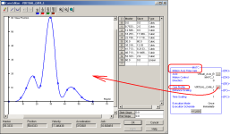
I'm sort of reading between the lines here – but the statement above makes me think that the following screen shot might bring up some ideas that you'd enjoy tinkering around with ... note that you can run stuff like this on the RSLogix5000 Emulator - and graph the "virtual" responses with the built in trending feature ...

party on ...
.

Motion_Profile.PNG
 
Last edited:
That example above shows another option for the master. The master can be time as well as another physical or virtual axis. Notice that it says "Motion Axis Time Cam". This is the simplest way to execute a cam table or spine.

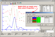
The example above appears to only show position. It should be possible to show the velocity and acceleration too. The problem with simple implementations of splines or cam tables it that the user cannot set both the velocity and acceleration to the desired value. This is important when stopping and starting as the velocity and acceleration should both be zero.
When doing cyclic motion the first and last point should have the same position, velocity and acceleration. I mentioned above that "Numerical Recipies in C" has that algorithm.

I like to think of cam tables as non-linear gearing.

So drbitboy, I have an x y table with a series of x y points like one might expect when executing G code. How does one make sure that one maintains a constant feed speed?
 
from Peter Nachtwey ...

The example above appears to only show position. It should be possible to show the velocity and acceleration too.

yep ... and please keep in mind that this particular "profile" is just an example demo of some squiggly lines ... specifically, this is NOT taken from a working program ... still - it's kind of fun to drag the little dots around and watch the various values change ...

so, Peter ... how's the retirement going for you? ... personally, I'm starting to get used to it ...

stay safe ... stay well ...
.

Graph_Properties.PNG
 
So drbitboy, I have an x y table with a series of x y points like one might expect when executing G code. How does one make sure that one maintains a constant feed speed?


I need to break out a pen and paper, but as a quick guess is the following close?

x' x'' + y' y'' = 0

That comes from

dSpeed/dt = d(x'**2 + y'**2)/dt = 0

The 2's drop out of course. It ignores the radius of the business end of the bit, of course, but to first order it's probably close enough.
 
Last edited:
Hi Ron, Peter,
Wow, so the Master "axis" value is no more than an arbitrary number then. This could have applications beyond motion control e.g. the recent bag-filling thread.
Thanks!
Yes, that is the whole point! The previous definitions were a little restricted. The rate of indexing through the X axis can change.

I can't figure out what you are trying to do. Yes, the rate of change of feed speed must be 0 but what about the index, x?

Look at Ron's example. How would you keep the feed speed constant? Ron's cam table shows places were the speed increases rapidly. This is because the x scale is indexing at a constant rate.

Another example. An operator has a teaching pendent. He can jog the three axes, x, y, and z to different points and then hit enter. The motion controller will save the points but what is the distance in time between the points? The operator doesn't have control of the speed between points. What ensures that the speed between the points is constant and at the desired speed?
 
from Peter Nachtwey ...

yep ... and please keep in mind that this particular "profile" is just an example demo of some squiggly lines ... specifically, this is NOT taken from a working program ... still - it's kind of fun to drag the little dots around and watch the various values change ...
Notice that the velocities and accelerations at the end points aren't both zero.


so, Peter ... how's the retirement going for you? ... personally, I'm starting to get used to it ...

stay safe ... stay well ...
.
I am going "camping" next week. It seems there are constant interruptions that get in the way. What I have learned is to schedule everything at the first of the month so the rest of the month I am free to go camping.

Most of the time I ride my bike or practice motion control with a table tennis ball.

I am still "working" about 20 hr/month at Delta.

There are trade shows scheduled. I will miss my first sawmill trade show in over 35 years.

How about you? I still have the "hotrod" examples from 2005.
For all the youngins

The "hot rod" was a wood burning iron that Ron used to teach temperature control.
The examples for ML1500 and SL500 are still in the misc area of the download section on this site.
 

Similar Topics

Hello all, I'm looking for ideas or solutions on having a industrial webcam or IP camera that we could use on our equipment to help monitor and...
Replies
4
Views
1,209
Kindly, I was trying to use the Motion Arm Output Cam (MAOC) instruction on a Rockwell plc, but I need to have it in a general AOI function. So, I...
Replies
1
Views
1,022
If a polynomial is used in a cam-profile for motion control, you normally have the option to displace the inflection point from the standard 0.5...
Replies
1
Views
1,440
I have submitted this tread to a magazine and it got rejected by the editor that obviously has never done motion or used cam tables.
Replies
6
Views
2,108
Hello to everyone. There is an inductive sensor to control the angle on the "Balluff bsw 819" rotary cam switch in a 1000 ton mechanical press...
Replies
0
Views
1,116
Back
Top Bottom