Mitsubishi Q-series: Setting a pump alarm

Mas01

Member
Join Date
Oct 2020
Location
Leicester, England
Posts
1,108
I've got 4 float switches in a water tank.
At the bottom of the tank is a pump which pumps water out of the tank (to circulate it in our water cooling system).

Here's a schematic:


[Water inlet here at 200cm ]


----float switch @180cm (X180)
----float switch @147cm (X147)

----float switch @100cm (X100)


----float switch @18cm (X018)
[PUMP OUTLET HERE ( 5cm off bottom)]
--------------Tank Bottom----|


I want to set a pump alarm when the water level is DROPPING, specifically as soon as the switches at 180/147/100cm are all FALSE, and the one at 18cm is TRUE. To warn the user that the water level's dropping, and to turn the pump off before it gets too low.

However, I don't want the alarm setting when the tank is filling up from empty.
I can't think of the logic that will do this, i.e. make the distinction between water level falling and water level rising.
 
Last edited:
Just set up the logic run as you described. it will only trigger in that state. The indeterminate position between that and all false will not matter for falling or rising. the alarm will go silent when any of the three false ones come back.

Is this for a class project?
 
Just set up the logic run as you described. it will only trigger in that state. The indeterminate position between that and all false will not matter for falling or rising. the alarm will go silent when any of the three false ones come back.

Is this for a class project?

No mate, this is for a live system (or one that will be live once I've added this logic).
 
Practically, I agree with Nova5: if an operator sees the alarm, turns off the pump, and then the level starts rising and the alarm goes off, they might be encouraged to turn the pump on, which would immediately trigger the alarm again. Rinse, repeat.


That said, if the pump is off AND we assume there is no leak AND we assume there is fluid coming into the tank from elsewhere, there is no need for the alarm, so you could AND the [X018] bit with a [Pump Is On] bit and send the result the [Alarm On] bit to get what you want, i.e. turning the pump off will stop the alarm, and the level will be rising if the pump is off if we assume that there is no leak and that there is fluid coming into the tank from elsewhere. But those are assumptions not measurements, so caveat emptor, and it is still a bad idea.
 
Last edited:
Need a bit more information for example does this tank auto fill i.e. when process is started will it maintain level from the water source?
If not, then there must be an initial fill before the cooling water is used.
or is it normally maintained by auto fill.
I assume that on initial fill all sensors will be off then it will fill to high level (which one is the top level a warning high level or fill level) ?.
You could set a bit when filling and reaches high level this bit tells you it has filled, AND this bit AND Pump Running AND not 100mm level = set alarm, reset fill bit.
On stop of pump, Reset Alarm.
But this is a guess, really need to know what fills the tank is it normally maintained or is it manually filled etc.
Also as this is cooling water, so you stop the pump feeding the cooling water to your process, does this need to stop the process as the pump not running will mean your not cooling the process isn't this a problem?
Need a flow of the process for example
On initial start of the process the cooling tank is filled before the process operation
once filled to level the feed then maintains the level in the tank.
If the water level goes below 100mm the process should stop (or does it maybe it only stops when low level is reached)
If the level drops below 100mm and the tank is auto filled then this is an alarm condition, so you stop the outlet pump how do you fill it do you also stop the process ?
So many questions we cannot answer without a detailed description on how the cooling water tank is filled etc.
 
Last edited:
I believe this is a closed system with water level maintained at about 160cm level. When not in use for a long period of time the tank is drained to prevent static water going stagnant and algal growth (tank is open topped and outside).
 
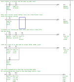
Not tried this but basically it sets a makeup bit if the level is not at normal level so disabling the alarm to fill the tank.
When the level drops below the 100cm level the alarm is set and if you wanted could stop the cooling pump (N/C alarm bit in pump logic.
Restarting the level makeup (assuming a button on screen) then this resets the alarm and starts the makeup again.
You will have to put in the relevant inputs & bit numbers for your process.

Alarm.png
 
Not tried this but basically it sets a makeup bit if the level is not at normal level so disabling the alarm to fill the tank.
When the level drops below the 100cm level the alarm is set and if you wanted could stop the cooling pump (N/C alarm bit in pump logic.
Restarting the level makeup (assuming a button on screen) then this resets the alarm and starts the makeup again.
You will have to put in the relevant inputs & bit numbers for your process.

Wow! I'll take a closer look at this at work tomorrow when I'm at work. Looks impressive!
 
I want to set a pump alarm when the water level is DROPPING, specifically as soon as the switches at 180/147/100cm are all FALSE, and the one at 18cm is TRUE. To warn the user that the water level's dropping, and to turn the pump off before it gets too low.

However, I don't want the alarm setting when the tank is filling up from empty.
I can't think of the logic that will do this, i.e. make the distinction between water level falling and water level rising.


We've all tried different alternatives, but the basic answer to this question is that the four float switches do not provide enough information to do what you are asking without some additional assumptions. Float switches only say if the level is above or below a certain point; they can say nothing about if it is increasing, decreasing, or staying the same (except at the point they change state, and this is only usable for the scan where it happens).


I assume there is no analog level sensor on the tank. If there was, you could check if the level was rising, e.g. take a sample every X seconds, and if the level increase then then disable the alarm. an alternative to the analog level sensor might be inlet pressure to the pump, although the process could affect the interpretation. That said, if that pressure is increasing (again, sample every X seconds to filter noise), then the level is probably increasing.
 
No, there's no level sensor in the tank.
There was talk of adding a pressure sensor near the bottom of the tank, but nothing definite on that.
 
Speaking to the point about running the pump after the lowest float is made again, I'd suggest using the [x100] float to reset the alarm, you could still silence it as suggested (pump off to disable the alarm). This is assuming you can silence and reset independently.
 
Speaking to the point about running the pump after the lowest float is made again, I'd suggest using the [x100] float to reset the alarm, you could still silence it as suggested (pump off to disable the alarm). This is assuming you can silence and reset independently.

Yes, there's a physical button to accept/acknowledge alarms. Pressing this will mute the audible warning.
There's also an alarm reset button on the GUI.
 
Last edited:
As your a beginner it is usual to slug the sensors with timers, this way it stops pumps running intermittently.
An example is if a tank uses the low level probe/sensor to stop an outlet pump from running the problem is often that the level falls below the sensor, however, when the pump stops the level tends to rise and may enable the sensor again so the pump will hunt. By putting a delay off timer on the sensor input means that it will continue to run the pump for x time until the sensor is completely uncovered, this is not always required if low/high latch is used, i.e. the low sensor turns off a latch but the high level sensor turns it on but often there will be a requirement to not wait until working level before starting the outlet pump.
This also goes for other types of sensors for example, a sensor that detects packs on a line, it may be the case where the sensor detects the pack but due to certain factors the signal switches on/off until covered completely, this can cause double or more signal transitions so could cause problems in the logic. examples are pack counts, signal to trigger say a depositor could cause a double shot on the depositor, others are a pack that has two compartments so the sensor sees the leading edge of the pack but half way through sees the gap between the compartments so assumes it is another pack, a number of ways to remove this is by slug timers to delay the signal i.e. a quick blip of the tray gap does not trigger an operation, the other way is to angle the sensor so it does not see the gap.
High High & low low levels in tanks are usually used as an alarm to say the tank has gone above or below what is safe, again these should be slugged a little so that they produce solid transitions, also often high high levels are wired normally closed (this is plc sense so when the liquid reaches the sensor the signal goes off, this is a sort of safe mode in the event of a wire dropping off the sensor etc. will loose the signal and stop the fill.
Some people like to latch & unlatch signals so only one bit as status but two timers, some do not like latches so each timer (delay on/delay off) controls separate bits rather than a single bit being set or reset.
Another point, this rig seems to be have a lot of operator intervention. I do not know the process but having a powerful PLC and HMI where the operator needs to press lots of buttons to get the system up & running seems a little weird, I would have thought that at the commencement of a test the operator does his usual checks to make sure everything is in place, presses the start button the control system then proceeds to fill any vessels, gets to the required temperature and checks all parameters are within tolerance then starts the test, messages on the screen for any operator intervention. As I said, I do not know the process so it may be this is the way it has to be done but I have been in this game for over 35 years & have come across many systems that could do with improvements that could have been implemented at the start.
The logic I posted is basic, and it may be prudent to add slug timers to the level sensors.
 

Similar Topics

how to communicate FactoryTalk Optix and Mitsubishi Q Series. I want to know the details of that
Replies
0
Views
36
In this sample programming, what does U4 mean? Any assistance would be greatly appreciated.
Replies
8
Views
273
Hi, I have a project with a R04CPU, RD77GF16 and a RJ71PN92 modules. The cell is given to me to change the program since the previous integrator...
Replies
9
Views
284
Hi One of the PLC's that I maintain/update is a Mitsubishi Q-Series, probably installed about 10 years ago. At the moment, ALL the wires from...
Replies
13
Views
1,170
Back
Top Bottom