How to use Modbus with TSX3721 Micro

joigunni

Supporting Member
Join Date
Jan 2011
Location
Iceland
Posts
52
Is anyone out there who know how to configure PLC TSX3721 Micro (v5.1) so my PC can read modbus from it. I have a Modbus Tester but it can't see my PLC-system. I'm not sure how to set up the PLC device ID (but I think the Id number is 1). Maybe I need to do some command that sends out modbus to my PC, is that possible. I am pretty sure that the connation between my PC and theTER-port on the PLC is right, pin 5 and 7 connect together (have a test program on my PLC that sends Character-string over to my PC system and it works).

I've never worked with Modbus but I gather that the "% MW: x" variables in TSX3721 is the same as modbus memory locations 40000x, but how do I read that memory locations from the PLC system and put it in modbus-memory locations. There some talk that it needs to install a PCMCIA Modbus in to TSX3721, others talk about TSX3721 v3.3> can talk modbus, and I have v5.1.

I am trying to connect TSX3721 Micro v5.1 with Citec/Scada v7.2 through the serial on PC machine.
 
You can use ter port to modbus on TSX 3721 PLC. Another method is use PCMCIA communication card as you mentioned.


If you want use ter port, you only need configure ter port to use modbus communication. Double click ter-port on rack view, then select channel0 = modbus link and give parity, baud rate, slave numeber.
This is all what is needed if you want that PLC is modbus slave.


Term port is RS485 so you need RS485/RS232 converter for PC, but I think your cabling is correct allready, because you can send characters.
(You need pins 1,2 and 5,7 of minidin8 connector. 1=A, 2=B and connect pins 5 and 7 together.)


Check ter port configuration from PLC program.

P.S

If you have programming cable TSXPCX1031, you can use it also for modbus communication, if you put rotation switch to postion 3
 
This is not working. I have a programming cable TSXPCX3030 (USB).
I've test modbus with a Tester called Mbus, where I got no response, and with modbus-Tester called Modnet, where I get some feedback when the programming cable is set to 0, I just do not quite understand this Tester. I have also used at Tester from Schneider in (Drvers managment Properties), where I get no feedback at all.

In PLC configuration I set TER-port Channel 0 to Modbus / Jbus Link as Mast, Type as Slave, Speed at 9600bits, stop as 1bit, Slave number to 1, Data on the RTU and Parity on Even. Something else I can do.

Is it possible that thos Modbus-Tester can not talk to PLC-Micro because it is not using standard Modbus variables?
 
Last edited:
Setting should be ok.

Can you use RS232/485 converter instead?

I haven't tested USB cable for this.

Modbus addresses on PLC are

%M0 = Modbus 1
%M1 = Modbus 2

%MW0 = modbus 40001
%MW1 = modbus 40002
...

config.jpg
 
I'll try it tomorrow. But what is Modbus 1 and 2, I have not heard of it before, and do I need to define which Modbus my PLC system is 1 or 2, and where do I do that?
 
I meaned above modbus coil (bit) addresses 00001, 00002, 00003, 00004...

TSX3721 have bit addresses %M0...%M255, and if you want read/write also these bits, you have to use addressess 00001...00256 on modbus. Of course, you can copy these bits to words/integers and read only words from PLC.

%MWx variables can be wound from modbus memory area 40001 ->. %MW0 = 40001, %MW1 = 40002, %MW2 = 40003 and so on...
 
Last edited:
I managed to get Modbus-Tester to see the PLC-system (not using a USB cable, but directly connected to the PLC 422/232 converter). But I'm still having trouble getting Citect to talk to the PLC-system, think it is incorrect installation of Varaibal-Tags with me.
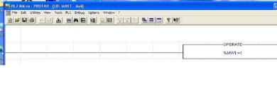
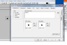
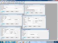
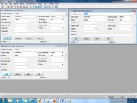
In Micro-PLC I put a "Operate-block" which looks like this "% MW1: = 1" in Citect I put a "Variable-tag" with the address 40002, and in Graphics I set a light bulb that will be read when the variable-tag is = 1.
See attached.
Can you see the bug?


Variable.jpg CitectVariable1.jpg CitectGraphics.jpg
 
I don't see error on attachments.

Have you configurated PLC, as earlier attachment? Also what is configation settings on Citec/PC.

Also is there dip settings (baud speed) on converter?

But you say, that you use 422/232 converter. PLC terminal port is RS485, so you need now 485/232 converter. (maybe there is dip switch for 422/485 communication on converter)


Not sure if this works, but tsxpcx3030 cable have switch (M/S), put switch to S-mode (slave) and try also with that cable.

I think that communication stops now to converter/cabling or configuration on citec is not correct.
 
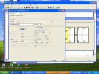
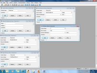
No, I was wrong, I have 485/232 converter and Dip switch are set to 9600, so it should be ok. I bring the following attachments with pictures of the settings, if you bother to check it for me. I'm getting a new firmware in the PLC-system, I'm going to run it in to tomorrow or the next day. Thanks for all your help.

PL7stilling.jpg Citect1.jpg Citect2.jpg Citect3.jpg
 

Attachments

  • Citect Communicatons.doc
    23.5 KB · Views: 70
I don't see any problems on configuration.

I don't think that firmware update will help, but you can try it. You have allreasy firmware on PLC, which is capable of use ter port with modbus.

Can you test communication with some other application (ex. with modscan) http://www.win-tech.com/html/modbus1.htm

If communication works with modscan, then problem is on citec configuration...

Also if you can, post your PLC program, I can test it with TSX3721 PLC.
 
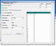
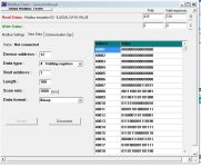
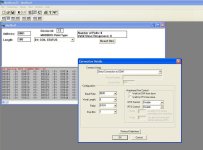
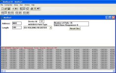
I have a modbus-Tester see Attachments 1 and 2. When I set the Data type on register, he comes with error messages, but still reads something.
There is also included in the attachments a PLC program. This is just a simple program to get communications up and running.

Modbus1.JPG 2.JPG
 

Attachments

  • test.zip
    6.4 KB · Views: 47
Try to read/write less registers att same time, when you use holding registers (ex. put lenght from 100 -> 40)
 
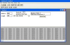
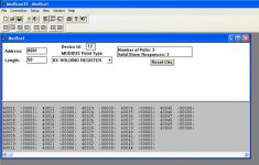
I tested your PLC program on tsx3721, I can read values from PLC, if I read less than 63 integers at one time.

If I try read ex. 63 - 100 integers, I get error on modbus communication. See attachments.

modbus1.jpg modbus2.jpg modbus3.jpg error_100integers.jpg
 
Yes, now my modbus-test works :p. Why do I need to have the integer value under 63, do you know whay, is it normal?
But one more thing I learned, was that my test-program is probably not working on my PLC-machine, the registers40001,40002 and 40003 is showing “0” not “1” as your test show.
Did you had to do any configuration of PLC-console when you start the program from me, I'm doing some nonsense here.
My PLC was running an old program that was written for much older machines, it worked well. I have to find out why the PLC is not working with this program. Maybe it was / is the main thing. I'm probably already be looking at the wrong place all the time, and would probably still be there if you were not helping me, thanks again.
 

Similar Topics

Apologies for not being the best IDEC programmer. I recently was doing some inspections on a site that had 3 FC6A IDEC processors. The issue is...
Replies
0
Views
46
Good morning fellow sea captains and wizards, I am being asked to do the above and obtain 4 values from each slave, I know about the MRX and MWX...
Replies
22
Views
235
Hi all I need help on this As in my project used Schneider TM241 controller. Now I want to communicate Elite energy meter with controller by...
Replies
3
Views
108
Good day guys. I have a third party device with its Modbus registers which I want to copy/set up on a plc because I need to convert my Modbus tcp...
Replies
3
Views
120
I'm a beginner in the automation field and I've set up an automation system connecting several devices (datalogger, radio, etc.) via Modbus RS485...
Replies
5
Views
194
Back
Top Bottom