Control Panel suggestions

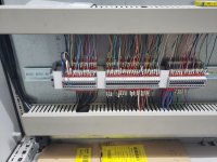
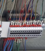
Panel looks nice. What are the blue terminals for?

Normally blue is used for intrinsically safe circuits, so it always throws me off when I see them and they're not separated.
 
Looks good to me...
Actually, aside from the extra terminal strips on the bottom half, and the use of MeanWell power supplies instead of AD's Rhino's, that looks almost identical to a bunch of panels I have build here to replace HVAC DCU's!


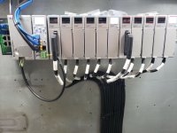
I don't add any extra terminals for the IO, I just connect directly to the ZipLink modules, and havent had any issues.


Nice work.
 
Disclaimer, since regulations are different over here vs over there, I might be wrong in some of my observations.

Things I think that must be looked into:

1. Even if it is only 120V, then I still suggest to use a main-switch that can be operated from the outside. If there are dangerous voltages inside an enclosure, and it is foreseeable that someone must open the enclosure for maintenance, then there should be a disconnect that is operable from the outside.
For such a small panel, you would use one that installs in the side of the panel, with the handle on the outside and the electrical connetions on the inside.

2. The circuit breakers before the 24V PSUs are single-pole only. Even though it is 'only' 120V + N, since the Neutral is current-carrying, both L and N should be disconnected - so 2-pole CBs.

3. How do you connect earth wires in cables connected at the bottom of the panel ? Even if everything in the field is 'only' 24V, you must be able to terminate the earth wires that go to 95% of all equipment.

4. I cannot see any labels on the PLC modules.

5. Do any of your cables use screens/shields ? If so, you must consider how to terminate the screen/shield. "Pigtails" are generally not allowed.

Things that are just my opinion:

6. The bottom part could be optimized to facilitate the cable connections better. The wire ducts seems to be on the small side IMO.
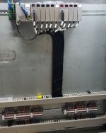
You have 4 vertical routes for the cables to enter the cabinet.
I suggest to have 2 central ladders where cables can go up, with terminals on both sides. Arranging the vertical cables in that way also saves space. Use the saved space for bigger wire ducts and/or greater space for the cables.

7. Screw terminals - yuck. I prefer cage-clamp for a number of reasons. One good reason is that they can save a considerable amount of space, without compromizing acessability. Because of connecting the wires from the front insted of under and above the terminal you save 40-50 mm per terminal strip.

8. What is the benefit of the PLC I/O via the ziplink modules ?? You have zero expansion capacity.
You have 32-channel modules with ziplink. How about using 16-channel modules and connecting directly on the PLC modules without the ziplink ?
 
I think I may have worded my initial response wrong. I thought this would work nice, and while it did for field wiring, I do not want to do it again. For reasons you mention and the amount of wasted time and space. I would like to find a better way to layout the ziplinks to wire direct with the commons organized so that field wiring isn't so messy(like my first attempt at wiring direct). Do you have any suggestions?

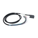
AD gives you a few options for the Zip-Link connections to PLC cards. You do not have to use their DIN-rail mounted Zip-Link PCB terminal strips. I understand your logic about not liking them and the placement of commons and such. I'm totally with you. What I did, was use their pigtail ZipLink cables (Example) and arrange my own field TB strip how I wanted. Now you have a lot of freedom. For example I used 3-tier TBs for my 24V inputs; This allows me to use tier 1 as a 0V/common, Tier 2 as +24V, and Tier 3 as my 24V digital input. Now all my 24V field sensors come in and terminate neatly all in one place, to a single TB. For other types of I/O I arranged my 3-tier TBs in other ways that made sense for the specific type of I/O. Note that this is a little more expensive than the ZipLink TBs, but a better solution in some cases.

I was under the impression it was a good idea to fuse each cards common? Each group of commons is simply that cards common. They're all still the same power supply, just fused that way. Is there a better way of doing this?
Depending on the type of card you're using, there is already a fuse inside the card.


EDIT: I forgot to say, your panel looks excellent!
Here I attached some pictures of how I did my TBs

EDIT2: fixed broken picture uploads

EDIT3: Ok nevermind I didn't fix them. I don't know what the heck is going on. I resized them all to be under the max size and still says 157 bytes and no image. Sorry. Just use your imagination. I give up.

EDIT4: Ok finally. Apparently when I resized them it just changed the pixel dimensions but for some reason not the file size.

ziplink pigtail.jpg 20190212_100818 (2).jpg 20190212_100822 (2).jpg 20190823_120702 (2).jpg 20190823_124703 (2).jpg
 
Last edited:
I agree that there is no need to wire from the blocks to terminals, waste of space, more chances of errors or faults. Also would reduce space needed & suggest all bottom entry of cables with plenty of room for installer to gland & dress cables, there is nothing worse than a crowded ducting for incoming cables as these are more likely to have to be replaced at some time i.e. damaged external cables. have you ever tried unravelling install cables from overcrowded trunking?.
 
Very clean work. We have been building panels for 35 years and a couple things i would suggest are:
1. Make life easiest for the installer. Put field terminal as close to the top as possible. Electricians hate crawling on the ground.
2. make field terminals vertical. Reason being when you look at them if their horizontal its easy to get the wrong terminal. But if their vertical its very obvious from top to bottom. Also its is a lot easier to stab a wire down then up or sideways.
3. Always take into account how many field wires are going to end up in the wire way. The fewer bends a field wire has to make the better.

4. Design the panel to fit the installation location taking into account top/side/bottom penetrations. Keeping in mind also if its wash down or meat handling which require slope top boxes.

When you say vertical are you talking about the orientation of the block itself(opposite of what I have at the bottom in this panel). This is the first time I ran the blocks in vertical columns(block itself horizontal) and found myself stabbing the wrong one a few times. I saw it on a lot of other panels and thought I'd try it. Not sure which was I like best.

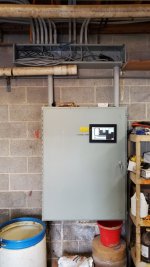
I'd prefer bottom entry even though its not a washdown environment. Everything was coming from above and the panel had knockouts up there already(I just buy used ones). It would've been easy to cap them, but I thought the top entry was cleaner even though it sucks to work with IMO. I attached a picture(cover off above because I was working on it) of this panel installed. The next one I have to make will be in a washdown environment so I need some ideas for side or bottom entry. All wires will originate from above panel. I don't know a good way of doing this. Conduit down the side with an LB would work I guess, but I'd like to see/hear some other ideas.

Thanks

PLC10.jpg
 
Last edited:
Disclaimer, since regulations are different over here vs over there, I might be wrong in some of my observations.

Things I think that must be looked into:

1. Even if it is only 120V, then I still suggest to use a main-switch that can be operated from the outside. If there are dangerous voltages inside an enclosure, and it is foreseeable that someone must open the enclosure for maintenance, then there should be a disconnect that is operable from the outside.
For such a small panel, you would use one that installs in the side of the panel, with the handle on the outside and the electrical connetions on the inside.

There's a kit for this disconnect to put the operator at 90* outside the cabinet IIRC

2. The circuit breakers before the 24V PSUs are single-pole only. Even though it is 'only' 120V + N, since the Neutral is current-carrying, both L and N should be disconnected - so 2-pole CBs.

I have two pole branch breakers sized for those PS sitting on the bench, not sure why I didn't use them. It may have been my original plan. Not sure, should be able to squeeze them in with a little re-arranging if needed though.

3. How do you connect earth wires in cables connected at the bottom of the panel ? Even if everything in the field is 'only' 24V, you must be able to terminate the earth wires that go to 95% of all equipment.
Multi level blocks

5. Do any of your cables use screens/shields ? If so, you must consider how to terminate the screen/shield. "Pigtails" are generally not allowed.

Analog have them, triple level blocks have the bottom level for terminating shields.

6. The bottom part could be optimized to facilitate the cable connections better. The wire ducts seems to be on the small side IMO.
You have 4 vertical routes for the cables to enter the cabinet.
I suggest to have 2 central ladders where cables can go up, with terminals on both sides. Arranging the vertical cables in that way also saves space. Use the saved space for bigger wire ducts and/or greater space for the cables.

The ducts are narrow, but tall(which I don't care for). I Would've liked a bit bigger, but last time I went too big. Bit of a Goldilocks right now trying to figure out the right size.

Two ducts would've worked nice with bottom entry and been cleaner/nicer to work with. I'm not sure how much space it would've saved though? I would still have the same number of wires requiring the same amount of room right?

With bottom entry I would've done the two routes like you suggest
7. Screw terminals - yuck. I prefer cage-clamp for a number of reasons. One good reason is that they can save a considerable amount of space, without compromizing acessability. Because of connecting the wires from the front insted of under and above the terminal you save 40-50 mm per terminal strip.

I agree, but when I started making some of these I bought screw terminals and still have a ton of them to go through before I can switch. I don't like the idea of having both types in the same cabinet so I'll wait until supplies are lower before I switch. Maybe that's bad thinking, but I'm cheap.

8. What is the benefit of the PLC I/O via the ziplink modules ?? You have zero expansion capacity.
You have 32-channel modules with ziplink. How about using 16-channel modules and connecting directly on the PLC modules without the ziplink ?

I'm not quite understanding you here. What isn't expandable? I agree on not wiring the ziplinks to TBs like I did and the space it wasted, but I'm lost on the expansion part. I don't know that I will ever come close to hooking up all of the I/O in the cabinet. I went through everything imaginable that I would ever want to automate where its located and its still less than 75% of the capacity. A number of those were just dreams too, not something practical. Some things I could automate but choose not to because they can be serviced by someone else if I don't touch it. Beneficial for certain things. I'm currently barely using 10% of it. The only other card I will likely add is another RTD and I have room for it, the wiring and TBs.

I do understand the concept of leaving room for expansion later, but I kind of did this one backwards with the expansion already built in. I realize that can cause other issues, but at some point I decided I just needed to do something and that it wouldn't be perfect.


Thanks
 
AD gives you a few options for the Zip-Link connections to PLC cards. You do not have to use their DIN-rail mounted Zip-Link PCB terminal strips. I understand your logic about not liking them and the placement of commons and such. I'm totally with you. What I did, was use their pigtail ZipLink cables (Example) and arrange my own field TB strip how I wanted. Now you have a lot of freedom. For example I used 3-tier TBs for my 24V inputs; This allows me to use tier 1 as a 0V/common, Tier 2 as +24V, and Tier 3 as my 24V digital input. Now all my 24V field sensors come in and terminate neatly all in one place, to a single TB. For other types of I/O I arranged my 3-tier TBs in other ways that made sense for the specific type of I/O. Note that this is a little more expensive than the ZipLink TBs, but a better solution in some cases.

That sounds like an idea I should look into. I like that idea for the Analog especially. For discrete I don't mind wiring to them, just need a few commons close by which I have a few ideas fore now, but then again maybe my thinking is wrong on having convenient commons.

Depending on the type of card you're using, there is already a fuse inside the card.

These are 15pt 1A output cards and one 32pt 100mA card. I've blown the 1A outputs before. A lot of reading found no consensus so I decided to fuse them so it was easier to find the faulty field device/wiring.

The next one I'm doing won't have much for 24VDC in the field. I plan on omitting the protection and using the 16pt 250mA output cards that have internal re-settable protection


Thanks
 
so what are the panels purpose?

This one runs a number of different things in a milking facility. Next one is a ventilation control.

Looks good to me...
Actually, aside from the extra terminal strips on the bottom half, and the use of MeanWell power supplies instead of AD's Rhino's, that looks almost identical to a bunch of panels I have build here to replace HVAC DCU's!

I don't add any extra terminals for the IO, I just connect directly to the ZipLink modules, and havent had any issues.

I bought the MW because they were cheaper and it felt like the panel was all AD. No real reasons really. I've used rhinos elsewhere. Any real opinion on the MW vs the rhino (I know they each have a lot of series so it may be hard to compare)?

Where do you locate the commons and such for the field wiring that doesn't terminate at the ziplink? I'm planning on doing that for the next one.

Thanks


This panel looks outstanding! If you ever want to quit your day job then I think you have a future.

I second that one! :geek:

I like it a lot.

Thank you. I like making these once in awhile, don't think I could do it daily.

First one I made that ran a fly sprayer

edited-image_zpsbeznkcfg.png


Second one, controls a winch based on a tone wheel for position with a limit switch for calibration/safety. Uses a Viper car remote start to control it because I'm cheap. Having 12 and 24 made a wiring mess though. Got a lot of experience programming button sequences to enter calibration modes and such. I don't plan on doing that again, with how cheap an EA3 HMI is I'll just put one of those in instead, much less screwing around.

PLC7_zpskb9bt9io.jpg


Larger panel in original post took over the fly sprayer as one of its tasks. Removed the fly panel and refit it with an EA3 and SSRs to run a doorway foamer. Next panel will take over the foamer and I'll just keep this thing for the next little project.

plc8_zpsbdxwv3y9.jpg


Used enclosure for the next project. Controls 39 motors for climate control in 5 rooms. (all 1/3hp and under).

edited-image_zpsfo7yaeeq.png
 

Similar Topics

Hi, If building a control panel in a 508a shop, when does it become a motor control center and fall out of scope for labelling under 508a? More...
Replies
1
Views
379
I would like to get some feedback from the forum regarding control panel wiring and in particular segregation of wiring. I happen to be part of a...
Replies
3
Views
836
Does anyone know of a good person/company that could troubleshoot an electrical problem in a control panel in South Carolina - tomorrow? If...
Replies
9
Views
2,193
I am very neurotic about control cabinet cleanliness. Unfortunately i have to convince my employer I nee to remove all of the precious spare...
Replies
10
Views
3,648
I'm being tasked with supporting / upgrading these panels but no software, cable, documentation. I have an old laptop running XP and would like...
Replies
4
Views
1,988
Back
Top Bottom