[HELP]ABB watermaster wiring and ladder logic to GE PacSys RX3i95

grinerjowker

Member
Join Date
Jul 2019
Location
Manitoba
Posts
4
Good morning folks,

I need your help and I am a beginner on PLC and I have been given an assignment on wiring a flowmeter to plc and create a logic to monitor the flow

1. I wanted to ask a question if the PLC interface attached below is the actual wiring of the output to the PLC?? do I need to provide a relay for this?

2. The task of this flowmeter is to monitor and totalize the flow of water using the pulse signal, how do I start to create a plc program for this, I am using GE Proficy Machine Edition 8.6 software?

Details:
flowmeter is FEW3
4 inches diameter
Q(0.4%) - 16.7 m3/h (73.4gal/min)
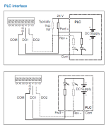
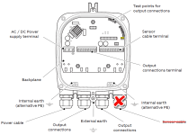
PLCinterface.png integratortransmitter.png
 
Last edited:
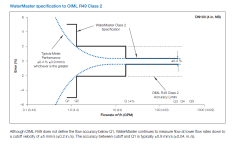
Correct me if I am wrong, basing on the attachment (flowmeter2.png) is Q4 the maximum flowrate of my transmitter? Because according to the diagram on (flowmeter3.png) it is the max amount of water exiting the sensor.

flowmeter2.png flowmeter3.png
 
I'm guessing that the Q categories meet a European norm for water metering; custody transfer, billing.

Q appears to be the nominal rated accuracy, 0.4%.

Q2 appears to be the lowest flow rate at which the meter is capable of the critical 2.0% uncertainty error (inaccuracy) which (I believe) is used as a limit for billing. I suspect that flow rates lower then the Q2 might have to be assigned 'low flow cutoff' for billing purposes, but I guessing at that.

Q1 appears to be in the flow rate range of ±5%, probably a lower acceptable limit; readings below which are just wild guesses.

I'm not sure what the breakpoint is for Q3

Q4 appears to be the maximum flow rate at which the meter will meet the nominal 0.4% accuracy spec, and which \is very likely the flow rate for maximum rated velocity. You can always force more water through a pipe or flowmeter at higher pressure/velocity, but the accuracy drops off at some point when the velocity exceeds the mfg spec.

I assume that the pulsed output you show in the wiring diagrams is a frequency pulse output, proportional to flow rate. If so, you should be aware that there is very likely a configurable setting in the meter that defines over what range your frequency/pulse output that represents the flow rate is scaled, like 1-1200gpm = 0-4,000 Hz, or whatever the frequency range is for this unit. Another brand calls the max value parameter for the proportional output Q Max, even though that is not the maximum the meter is capable of.

The alternative is a pulse output where the pulse toggles every time a give flow total is measured, for instance, one pulse every 10 gallons or one pulse every 200 gallons. It can be a challenge to derive the instantaneous flow rate from a total


Thank you for your response, I am asking for help from my colleague as well and from their perspective it is better to use the digital data(profibus/modbus) version than the digital output because it will create more problems when the totalizer reaches to a year span.

a question out of the blue is it better to use the Hart digital data for this instead of using the digital output? with that said, do you have any suggestions where I can learn hart digital data procedure from transmitter to plc?
 
Last edited:

Similar Topics

I am using a ACS800 regen drive to drive a 500hp motor for a engine dynomometer application. I am currently running the drive via ethercat...
Replies
0
Views
1,687
hi i try to do a simple program displacement program using PDispOn PROC move_up_back() PDispOn *, tool1; MoveL *, v500, z10, tool1; PDispOff...
Replies
2
Views
2,023
Hi, I want to send the data from ML1400 to ABB PLC. Can anyone help me to send the data through MSG instruction setup. Best Regards, Prasanna
Replies
1
Views
1,360
Hi i need your help , Please tell me what is the meaning of 14<<2 and other , thanks
Replies
0
Views
1,238
sir plz tell me how to interface servo motor with abb micrologoc 1400b plc plz give me detail of instruction and wht type driver may i use or tell...
Replies
5
Views
2,498
Back
Top Bottom