You are using an out of date browser. It may not display this or other websites correctly.
You should upgrade or use an alternative browser.
You should upgrade or use an alternative browser.
Flip flop circuit
- Thread starter Jenny8711
- Start date
Steve Bailey
Lifetime Supporting Member + Moderator
In the top branch of rung 1, the -]/[- "Z" contact should be "B".
widelto
Member
see my collection
Jenny:
Welcome to the forum.
Attached you will find my flip-flop collection, hope it will help you to understand them.
Best Regards,
william
Jenny:
Welcome to the forum.
Attached you will find my flip-flop collection, hope it will help you to understand them.
Best Regards,
william
the_msp
Lifetime Supporting Member
Welcome to the forum, glad you got it sorted.
A tip for more rungs of logic etc, for better visibility, press the [Windows] key + Shift + S, this will let you take a snapshot of the screen, then save that as a file and upload it here as an attachment.
A tip for more rungs of logic etc, for better visibility, press the [Windows] key + Shift + S, this will let you take a snapshot of the screen, then save that as a file and upload it here as an attachment.
geniusintraining
Lifetime Supporting Member + Moderator
A tip for more rungs of logic etc, for better visibility, press the [Windows] key + Shift + S, this will let you take a snapshot of the screen, then save that as a file and upload it here as an attachment.
Or.... ALT and print screen then paste in MS Paint and save, but whatever flavor ice cream you like as they all work :site:
As an aside -
Prior to your correction -
If you break down what the top branch of Rung 1 was saying, "If Z AND NOT Z", you'll see that branch should never evaluate as true.
You may in a real program see that used to 'set' a coil to be always false. This can be handy in places.
Prior to your correction -
If you break down what the top branch of Rung 1 was saying, "If Z AND NOT Z", you'll see that branch should never evaluate as true.
You may in a real program see that used to 'set' a coil to be always false. This can be handy in places.
Last edited:
Thanks everybody, I have checked all the posts 
For clarification, I understand that closing switch A is detected by the coil at B.
But which bit does this coil act on to make Row 1 true and the output Z true?
Sorry for the noob questions!
For clarification, I understand that closing switch A is detected by the coil at B.
But which bit does this coil act on to make Row 1 true and the output Z true?
Sorry for the noob questions!
Firejo
Member
Here is what I believe is meant to happen. Anybody feel free to correct me if I am wrong.
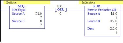
Row 0 - When A is energized THEN Coil B is energized, but only for one scan cycle. That is what makes the flip flop work. (I am guessing that the P inside the coil means pulse)
Row 1 - When Z is energized AND B is de-energized THEN Coil Z is energized. This will be the row that keeps Coil Z energized.
Row 2 - When Z is de-energized AND B is energized THEN coil Z is energized. This is the row that energizes coil Z initially when you turn on A.
When coil Z is de-energized, pressing Button A energizes Coil B for one scan. This makes Row 2 true for one scan. This energizes Coil Z. Since Coil B is pulsed, even if Button A is being held down, Coil B is no longer energized. Since Coil Z is energized and Coil B is not energized, Row 1 is true and Coil Z remains energized.
Now release Button A and press it again, Coil B will once again be energized for one scan. This means that on this scan, Coil B is energized and Coil Z is energized. Looking at the conditions to energize Coil Z (Row 1 and Row 2) there is no condition that says "IF Z is energized AND B is energized" Coil Z will no longer remain energized. Once you release button A, the circuit is back in the place where we started.
In the photos that you have provided row 1 currently says; When Z is energized AND Z is de-energized, coil Z is energized. This is a problem because Z cannot be both energized and de-energized at the same time. What is likely happening when you try to run this is that Row 2 is true when you press button A (remember that this means Coil B is energized for one scan), Coil Z is only energizing for one scan cycle. On the next scan Coil Z is energized but Coil B is not. This means Row 2 is now false, and since the inputs in Row 1 can never evaluate to be true, Coil Z cannot be energized. This could be happening in microseconds, so you would never see it.
One way to see this in action would be to add a counter to your program that will count up every time Coil Z is energized. If you leave Row 1 the way it is, the counter should increment each time you press Button A. If you change -|/|- Z to -|/|- B, you should see the counter increment every other time you press Button A, meaning the flip flop is working as intended.
L D[AR2P#0.0]
Lifetime Supporting Member
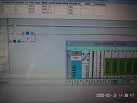
Var B is defined as an input, I would re-declare it to be an internal memory bit (M)
(as an aside, the simulator for this plc will not run on my Win10 laptop as my Virus Protection detects a Trojan)
(as an aside, the simulator for this plc will not run on my Win10 laptop as my Virus Protection detects a Trojan)
Last edited:
Mike Lamond
Member
Here's another handy bit of logic, even if it looks like illogic at first. D will continuously toggle on one scan and off the next. It's useful for counters and other instructions where the input must be retriggered to repeat the action.
Mike
   D            D

--|/|----------( )-
Mike
Similar Topics
I am having this issue trying to figure out how to do this. I have a Hydraulic ram that travels when a machine is running. The ram extends to the...
- Replies
- 31
- Views
- 9,531
I found and fixed issue. B3:3 was used in MOV.
- Replies
- 11
- Views
- 2,592
I am calculating power factor from samples of voltage and current. Calculation is done by multiplying voltage and current samples. What Im...
- Replies
- 0
- Views
- 1,647
Hi all,
my first post here, I've been lurking for a while.
I'm a beginner and I hit a wall on one of my first projects I'm working on.
I know it...
- Replies
- 6
- Views
- 2,549
Hi Everyone,
I am trying to write a flip flop circuit with one input that changes the state of two outputs. If I press the button once it brings...
- Replies
- 3
- Views
- 3,257


