Ladder Logic Help

NickH21

Member
Join Date
Feb 2018
Location
Cincinnati
Posts
12
I need help on this question:

Use the Door Simulator in Logix Pro to implement a program that will automate the garage door opening and closing process. The sequence of operation is as follows:
• Initially, the garage is closed
• When the OPEN button is momentarily depressed, the garage door will open
• When the door reaches the top limit switch, it will pause for 10 seconds, and then automatically close
• The OPEN indicator light will activate only while the door is traveling upward
• The SHUT indicator light will activate only while the door is traveling downward

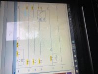
The pictures posted are of my solution right now and also what the door simulation looks like in the program software.
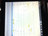
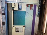
39ADB772-7041-4A90-BA9B-4E6613A5E329.jpg 09A41EB0-2EBD-489D-A1CB-D7C8CBF0499E.jpg
 
welcome to the forum.

It would help everyone if you would define what your I/o is so we do not have to guess at what you have done.
thanks for showing your work that you have done so far !!
you have put forth effort rather than asking for help up front.
you are almost there.
Look at your indicator rungs, what turns them on?
In your description, what did you want the lights to do?

james
 
Last edited:
welcome to the forum.

It would help everyone if you would define what your I/o is so we do not have to guess at what you have done.

james

I:1/0 - Open Limit Switch
I:1/1 - Close limit switch
I:1/2 - open push button

O:2/0 - Motor up to open
O:2/1 - Motor down to close
O:2/2 - motor light ajar
O:2/3 - motor open light
O:2/4 - motor close light
 
May I suggest that you label your logic and then look at what you have.
things will look much better to you when you have done that.

Reason,
what your ladder logic says versus what your descriptions are do not match.

james
 
May I suggest that you label your logic and then look at what you have.
things will look much better to you when you have done that.

Reason,
what your ladder logic says versus what your descriptions are do not match.

james

I:1/0 is open light
I:1/1 is close light
I:1/2 is stop light
I:1/3 is open limit switch
I:1/4 is close limit switch

I updated my program to reflect that

AA12651D-BDD5-4A3F-99F6-F8D68B14A8EB.jpg
 
Please Zip and post your .rsl file from the LogixPro software, others on the forum have the software and can contribute. Also, for examples, see the "Downloads/Allen Bradley section. Downloads button is at the top of the screen. Then scroll down for Door Simulation (.rsl) files. Here is a convenient link to reach that section.
Link:
http://www.plcs.net/downloads/index...i4&direction=0&order=&directory=Allen_Bradley

Thanks i'll check that out. I posted the zip file.
 
At first glance I don't see a TON for the T4:2/DN bit in the 000 rung and don't understand what you are trying to do with it. I am guessing that you may have numbered the "DN" bit incorrectly. If it is part of reclosing the door, I would suggest correcting the "DN" bit timer number, change the location of it to be in the branch with O:2/0 that is around the Open PB in rung 000 and the condition from open to closed.
 
Last edited:
At first glance I don't see a TON for the T4:2/DN bit in the 000 rung and don't understand what you are trying to do with it. I am guessing that you may have numbered the "DN" bit incorrectly. If it is part of reclosing the door, I would suggest correcting the "DN" bit timer number, change the location of it to be in the branch with O:2/0 that is around the Open PB in rung 000 and the condition from open to closed.

Yea I must have missed that. I updated it in the file, but it doesnt seem to change anything. When I download the program and then run it, the close and stop lights stay on and i dont know why. Has to be something to do with rungs 001 and 002.
 
I have noticed that the Door Simulation does not behave as expected due to the mechanical state of the Limit Switches. I am also trying to program a working solution. I first programmed a manual push the up button to turn on the up motor output in order to figure out what is going on. I would suggest to start over and use just the open button and open motor output as a beginning, then add one device such as a limit switch and test until you get that working.
 
Last edited:
Alright I think thats the best thing to do. The tricky thing is to have it delay 10 seconds and then close automatically, but ill keep working. Let me know if you come up with anything. Thanks
 
I've got a working solution but the other forum members would frown on me to simply post the working answer since you are trying to learn. I will continue to give you hints and also correct any errors for you.
As I said earlier, get the up rung working manually then the down rung. After that you can add the Limit Switches to stop the door from going too far. Next,make new rungs for the "Open" light, "Close" light, and the "Ajar" light. I did the lights a little different in that they would only be on at fully open or fully closed. I suppose that they could be programmed to function as you indicated in the post #1 but the simulator is not letting me do that. I used the Ajar light to be on while the door was traveling. Next make the timer rung using the "Open" Light to turn on the timer. Use the timer done bit to push the "Down" button. Use the motor output for the "Up" to latch in the "Up" rung and use the motor output for the "Down" to latch in the "Down" rung. It's kinda hard to write exactly what I'm trying to say but maybe these hints will help you understand.
 
Last edited:
Just a quick update. I was able to eliminate the "Ajar" light and used the motor outputs to turn on the "Up" and "Down" lights.
 
Just a quick update. I was able to eliminate the "Ajar" light and used the motor outputs to turn on the "Up" and "Down" lights.

Thanks so much for all the help. Ill be in class throughout the day, but i was able to work on it a little bit this morning and Ive got it to open and close manually without going to far and having the motor stall. Next ill work on the lights. Thanks again
 
Thanks so much for all the help. Ill be in class throughout the day, but i was able to work on it a little bit this morning and Ive got it to open and close manually without going to far and having the motor stall. Next ill work on the lights. Thanks again

This is what ive got so far. Im getting confused on the timer rung. Not sure how to implement that.
 

Similar Topics

Working on project will update after it is completed.
Replies
2
Views
350
Can someone help me piece this problem together. I have a lot of it down I think but cannot seem to get it right. Probably an easy one for most on...
Replies
1
Views
299
Hi everyone, I'm working on a project that involves using a Keyence LR-X100 sensor in Studio 5000 V35 ladder logic to determine the object's...
Replies
4
Views
669
Hey. I am new to PLCs and LogixPro. A friend and I have been trying to build this diagram and instructions using LogixPro500. Could anyone help us...
Replies
15
Views
1,253
I need to know how to take a schematic like this and solve it for let’s say a run time of 5 seconds By solve I mean determine which rungs are...
Replies
33
Views
9,094
Back
Top Bottom