Tubularfab
Member
Ok, first of all I must remind you that I am a complete newb to PLC programming of any kind. I am working on a digital angle control for a mandrel tube bender, and my first step is to use a standalone PLC (as in separate from the one currently running the machine) to monitor a quadrature encoder on the bender and pass the scaled bend angle over to the PLC. For learning purposes I am using this separate PLC for my expirimentation and my only output is closing a relay when the bend angle is reached. This relay acts as a limit switch input for the other PLC running hte machine. This way I have no chance of doing anything dangerous while I'm learning!
I have a Direct Logic 205 series PLC with the DL240 processor, a relay output card, and an H2-CTRIO high speed counter. I am using a 360 div/rev quad encoder in 4x counting mode to get .25 degree resolution. I also have a 6" Cmore color touchscreen for an HMI.
I have configured the CTRIO using the CTRIO workbench for quad counting, 4X and scaled the output to degrees which is then stored in a memory V location with one implied decimal place. I have an output box on the C-more displaying this angle real time, and it is working. I also was able to create a reset pushbutton on the Cmore that momentarily closes the reset bit for the counter - that functions correctly as well.
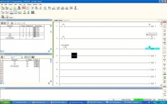
OK - I should qualify - this is all working if I manually tell the ctrio to go into run mode in the workbench. It stays in run mode as long as I don't kill power to the plc. What I'm not getting is what do I need to do in the ladder logic to initialise the ctrio and put it in run mode. The examples in the ctrio manual are all using a lot more functions of the ctrio than I need.
Second question - what type of scheme could I use to let me enter multiple setpoints for bend angles, and then toggle through them sequentially? I understand how to create a user input with the cmore and store the number in memory, but I don't know how to then access the numbers sequentially. In normal computer programming I'd envision a simple array holding the bend angles and run the process as a loop and increase the array reference by one each time through the loop. I have no idea where to start to do that on a plc - or even whether this would be done in the ladder logic or the hmi. Some hints on how to implement that would be great...
To recap how this works:
I might have a tube that has 6 bends in it. for kicks b1=24.2, b2=46.2 b3=5.6, yadda yadda. I go to the machine and manually position the tube for b1 then hit the BEND button (and wish to have the machine stop at 24.2 degrees. The clamps are then released, the bend arm swings back to zero degrees (hitting a limit switch) and then you position the tube for b2 and repeat. If the next bend angle setpoint is zero degrees that should signal no more bends and make B1 the setpoint again.
Thank you!
Last edited:


